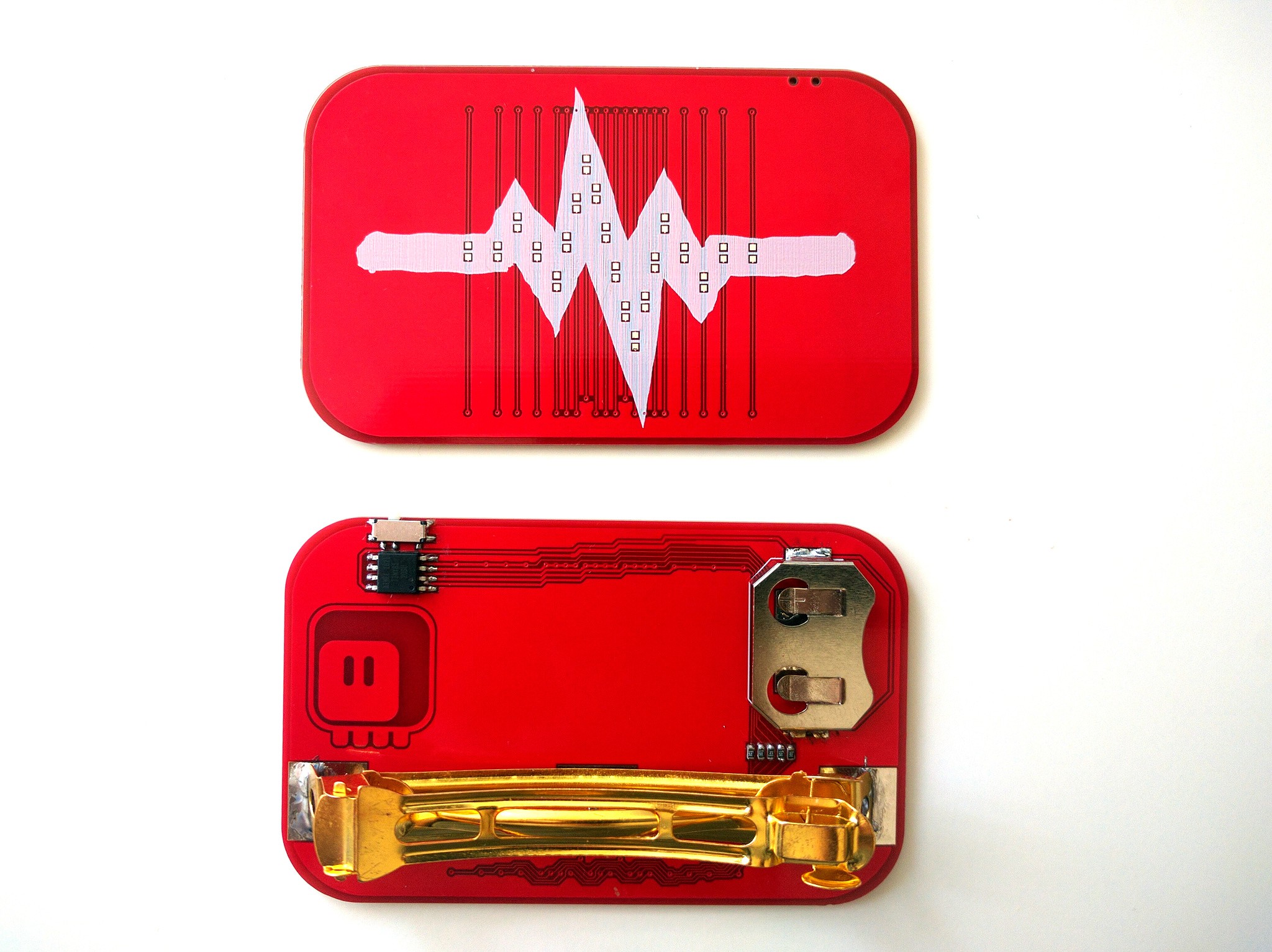
The PCBs arrived from @Elecrow today, and they look great.

There is one mistake I made — one of the traces is connected with one of the pads of the battery holder. That's what you get when you move the parts slightly just before sending the design for fabrication. Fortunately it's easy enough to cut the two apart.
With the hardware ready, I need the software. In this case this simple code for attiny13 works:
#include <avr/io.h>
#include <avr/pgmspace.h>
#include <util/delay.h>

#define byte unsigned char

#define COL0 PB0
#define COL1 PB4
#define COL2 PB1
#define COL3 PB3
#define COL4 PB2

const byte PROGMEM VALUES[] = {
    (COL0 << 4) | COL4,
    (COL0 << 4) | COL3,
    (COL0 << 4) | COL2,
    (COL0 << 4) | COL1,

    (COL1 << 4) | COL4,
    (COL1 << 4) | COL3,
    (COL1 << 4) | COL2,
    (COL1 << 4) | COL0,

    (COL2 << 4) | COL4,
    (COL2 << 4) | COL3,
    (COL2 << 4) | COL1,
    (COL2 << 4) | COL0,

    (COL3 << 4) | COL4,
    (COL3 << 4) | COL2,
    (COL3 << 4) | COL1,
    (COL3 << 4) | COL0,

    (COL4 << 4) | COL3,
    (COL4 << 4) | COL2,
    (COL4 << 4) | COL1,
    (COL4 << 4) | COL0,
};


int main() {
    while(1) {
        for (byte i=0; i<20; ++i) {
            byte value = pgm_read_byte_near(VALUES + i);
            DDRB = _BV(value & 0x0f) | _BV(value >> 4);
            PORTB = _BV(value >> 4);
            _delay_ms(18);
        }
        DDRB = 0;
        _delay_ms(740);
    }
}
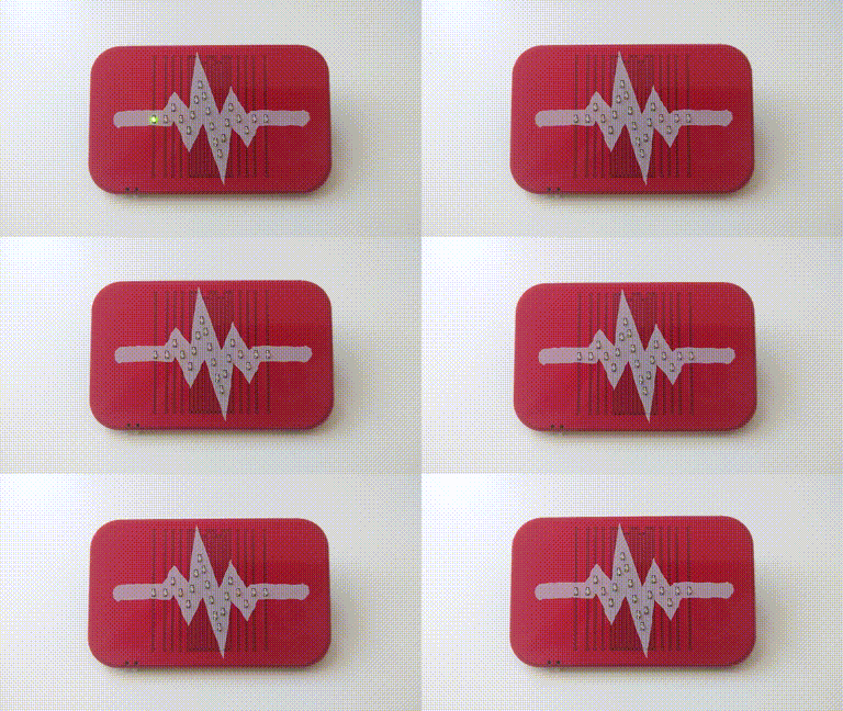
I made it a bit more complex than it could have been, but the basic idea is that I put the desired rows and columns for each LED in a table, and then I just loop over it to create the animation. It's really simple, I have no idea where the 150 bytes of flash this program takes come from. Oh well, it fits anyways. Here's a horrible GIF showing the animation:

Now I'm going to send it to a couple of people for testing, and I'm going to work on the actual "smart" barrette — the one that can control all your blinking jewelry.
 deʃhipu
Discussions
Become a Hackaday.io Member
Create an account to leave a comment. Already have an account? Log In.
Awesome design! Thanks very much for your sharing.
Are you sure? yes | no