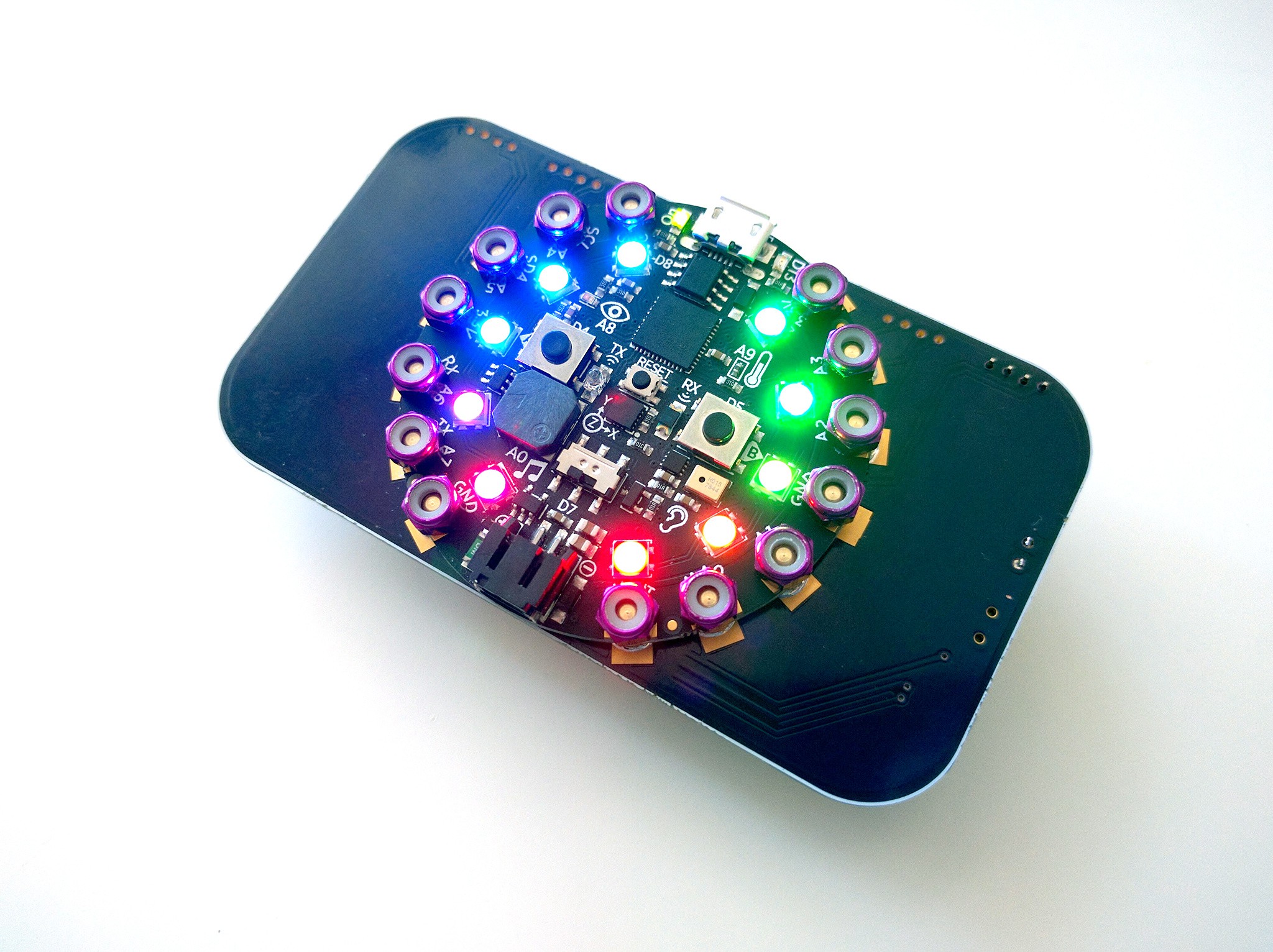
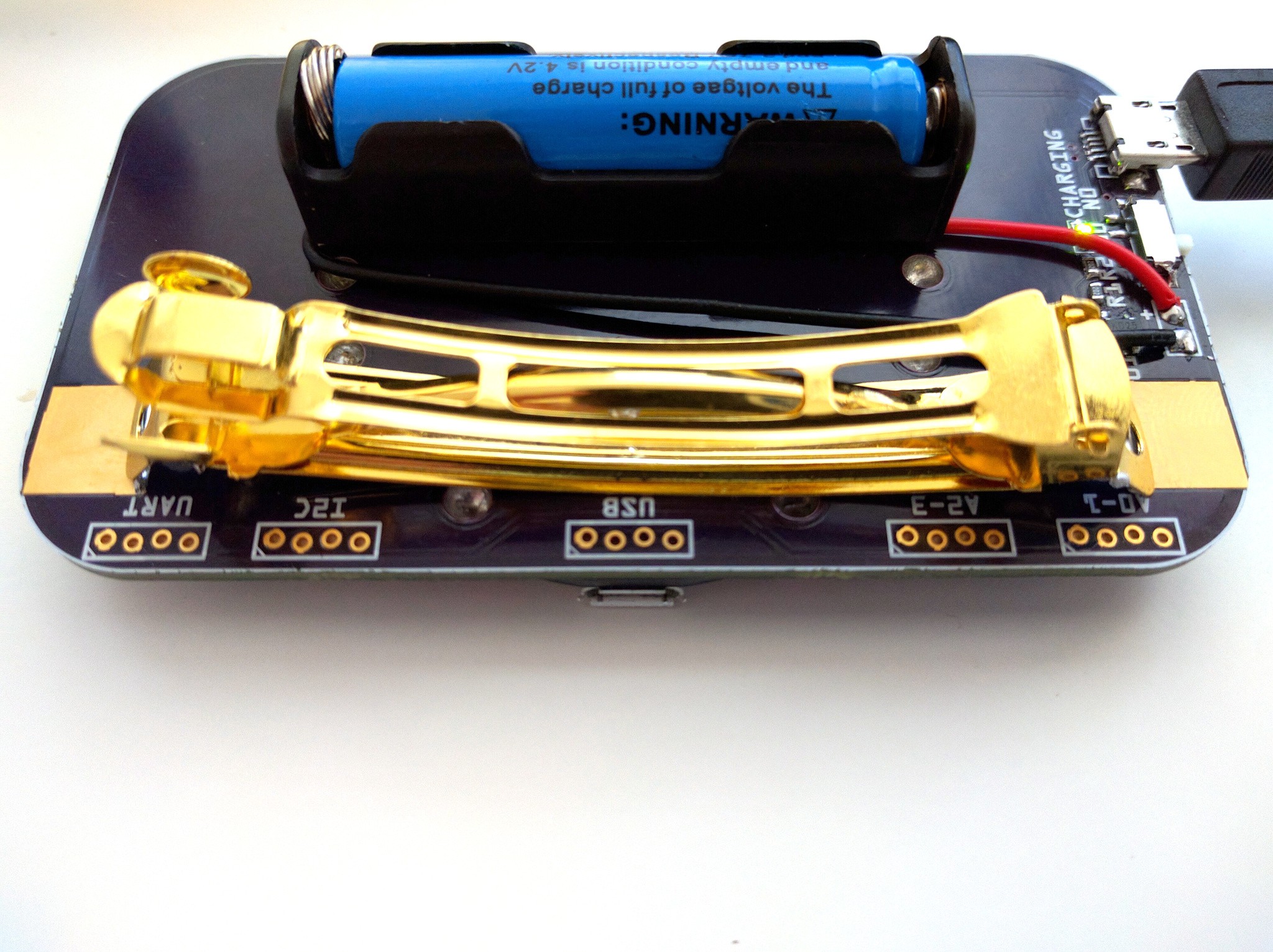
The PCBs just arrived from @oshpark and I finally assembled a proper prototype. I'm quite happy with how it looks, even without the face plate or any ornaments on the PCB:

In particular, I like how the holes covered with the soldermask look like: inconspicious. I used staggered holes for the connectors, which means that you can simply insert male pin headers into them — you can see one inserted in the top right corner. That really lets me hide them from view.
There are five connectors:

Four for general purpose GPIO pins, with two pins on each, also doubling for UART and I2C communication, and one for USB, for those devices (like the #Video Pendant) which are too small to fit an USB port, but still need USB communication. The power on the USB port is stabilized 3.3V, while the remaining ports are connected to the battery directly, because they are likely to need all the power they can get.
I will do some more testing with those connectors, and if they don't work well enough, I will solder either female pin headers, or grove sockets in there.
More importantly, the build instructions and parts list are now updated, and there is a bunch of new photos. Unfortunately I won't have time to update the video, but the basic functionality shown there remains the same (well, except for the battery charging, but that's a boring thing to watch).
The next step will be working on the ornaments and the face plate.
 deʃhipu
Discussions
Become a Hackaday.io Member
Create an account to leave a comment. Already have an account? Log In.
very nice!
Are you sure? yes | no