In order to be usable, we must be able to create a complete drive train using openwheels.
Indeed, the wheels placement must be precisely done depending on the track lenght if using tracks, and in all case, the drive gear mus be positionned precisely according to the driven wheel.
I don't want to leave the user to lots trigonometric calculation and fiddling to have a perfect adjustment, so i provide a way to design a drive train that can be integrated in a robot :

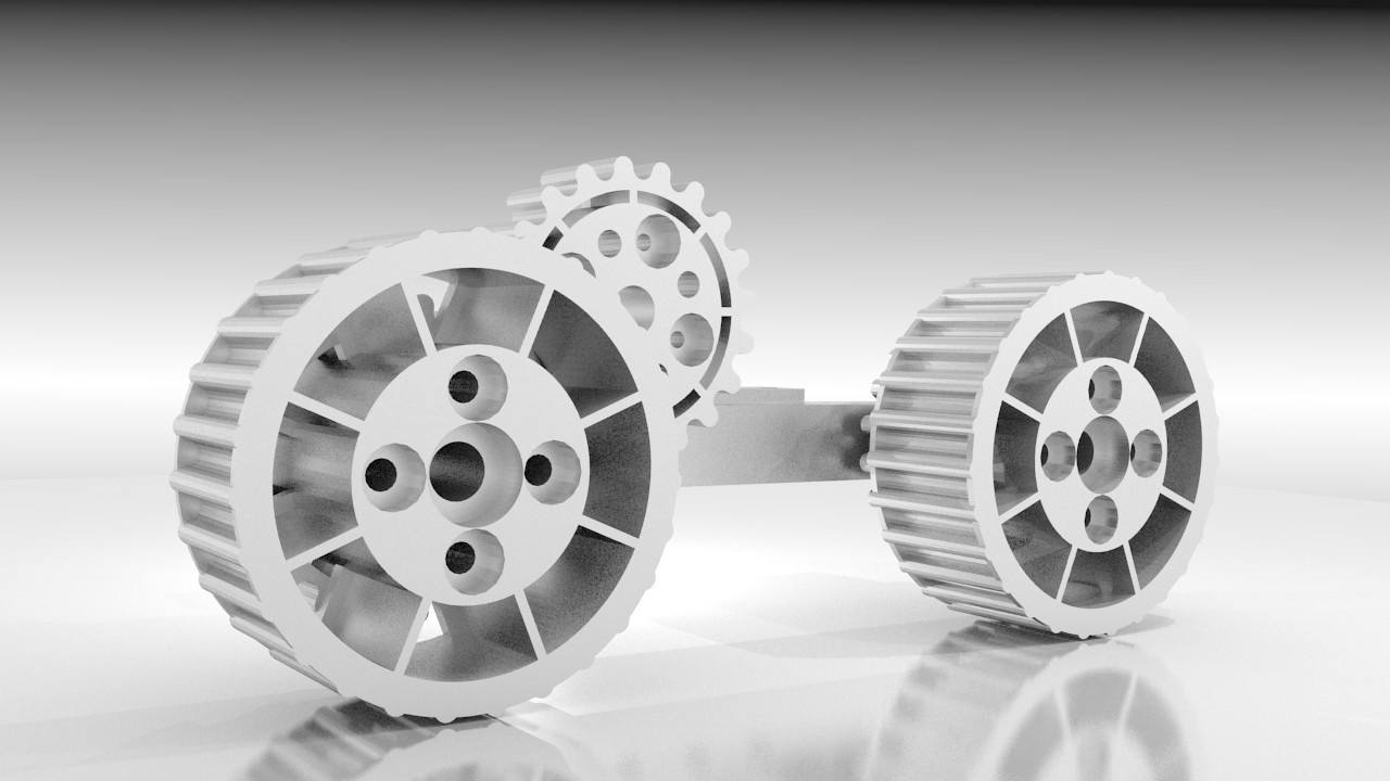
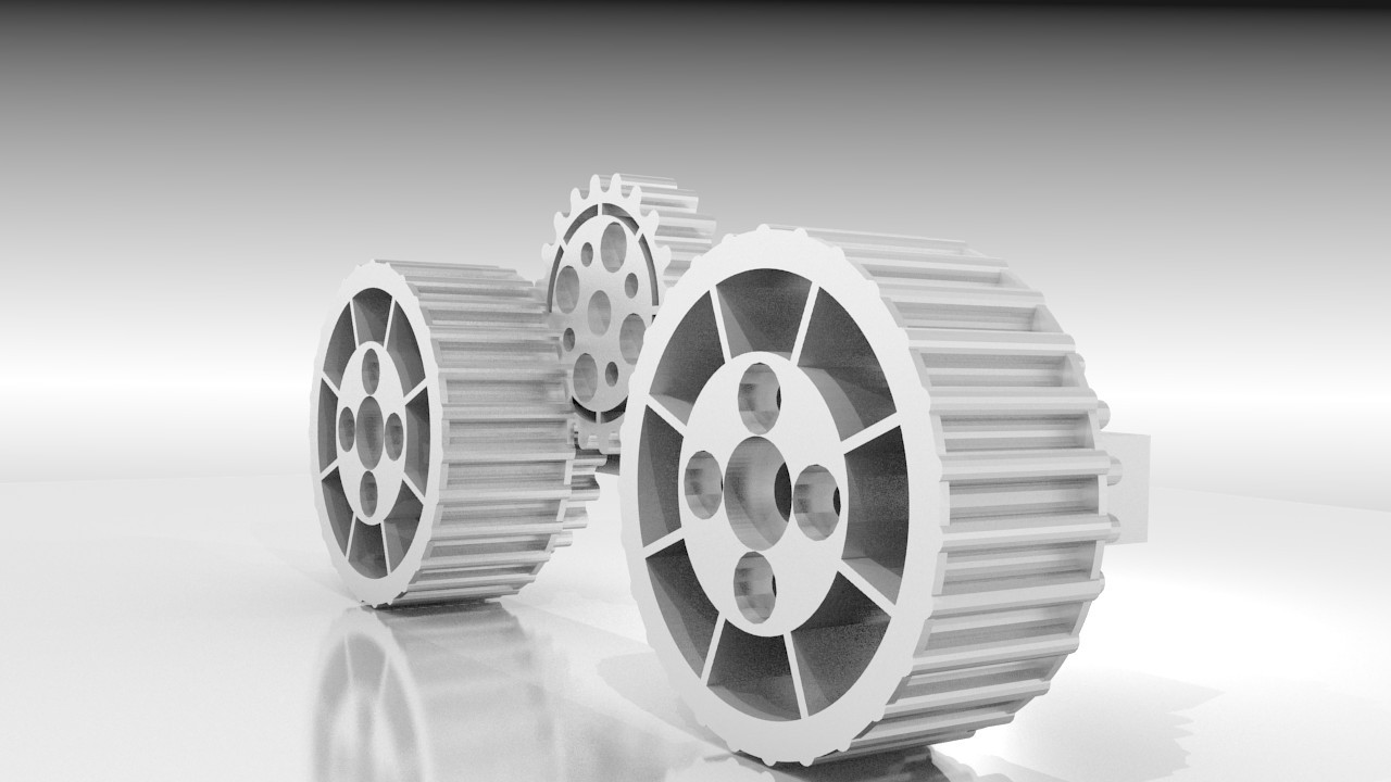
Again, this was designed in OpenScad, but i made a render in blender for a nicer visual.

On this picture, the 2 larger "gearings" are the wheels (the cogs are there to grip the track or the tyre), and a smaller gearing is directly behind the wheel. It is in direct contact with an identical gearing that is connected to the motor shaft.
The wheels and their associated drive gears are secured together with 4 screws, and secured to the chassis with a steel axle. The axle has a threaded end to screw it on the chassis, and a large, cylindrical head to lock the wheel in place along the axis, without keeping it from rotating.
That way, all the loads are applied on the wheels and the steel axle rather than on the motor shaft. It thus provide a far superior strength in this part (a plain 5mm steel rod for the wheel axle versus a 2.5mm D shaft for the motor in the best case, or a plastic servo for the most fragile)
It also makes it much easier to change the motors, since in that case, you have 2 screw to remove to unsecure the motor bracket, then installing the gear on the new motor, putting the new motor in an adapted bracket, then put everything in place with 2 screws!
It's not only to replace a broken motor, but also to change for a different model in an easier way.
 Audrey Robinel
Discussions
Become a Hackaday.io Member
Create an account to leave a comment. Already have an account? Log In.