Jan
Jan-
03 – test placement of components
08/11/2018 at 08:18 • 0 commentsEdit August 15th, 2018: Parts ordered.
All parts are ordered and are expected to arrive in around two weeks from china. I hope to finish my board this weekend to send it to the fab as well, so I can start my first assembly.
The final design will look quite different from the mock-up...
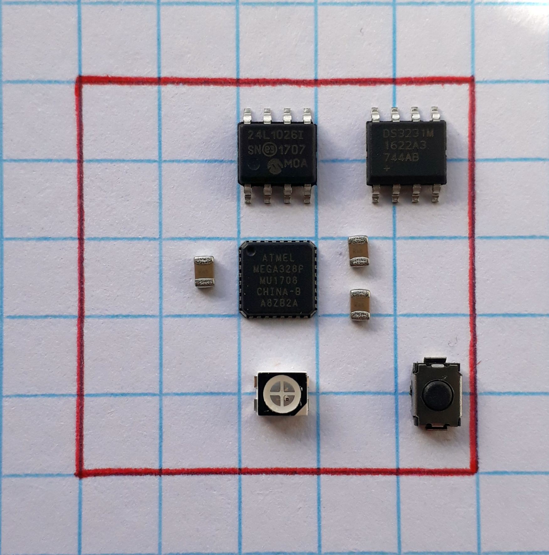
---------- more ----------The following pics show the test-placement of the components on a 25mm square:
![]()
Top side of "PCB" Always funny to see the how big "dumb" passives can be compared to e.g. the Atmega328 in its 5x5mm case. Caps are 0805, LED is PLCC4... As I will need to place a few other passives I guess I need to switch to 0603 or 0402 for this project. Soldering only one 0603 or two 0402 LEDs would save additional space as well.
Of course placement is just to get a broad overview of how much space I've got to play with, not final placement.
![]()
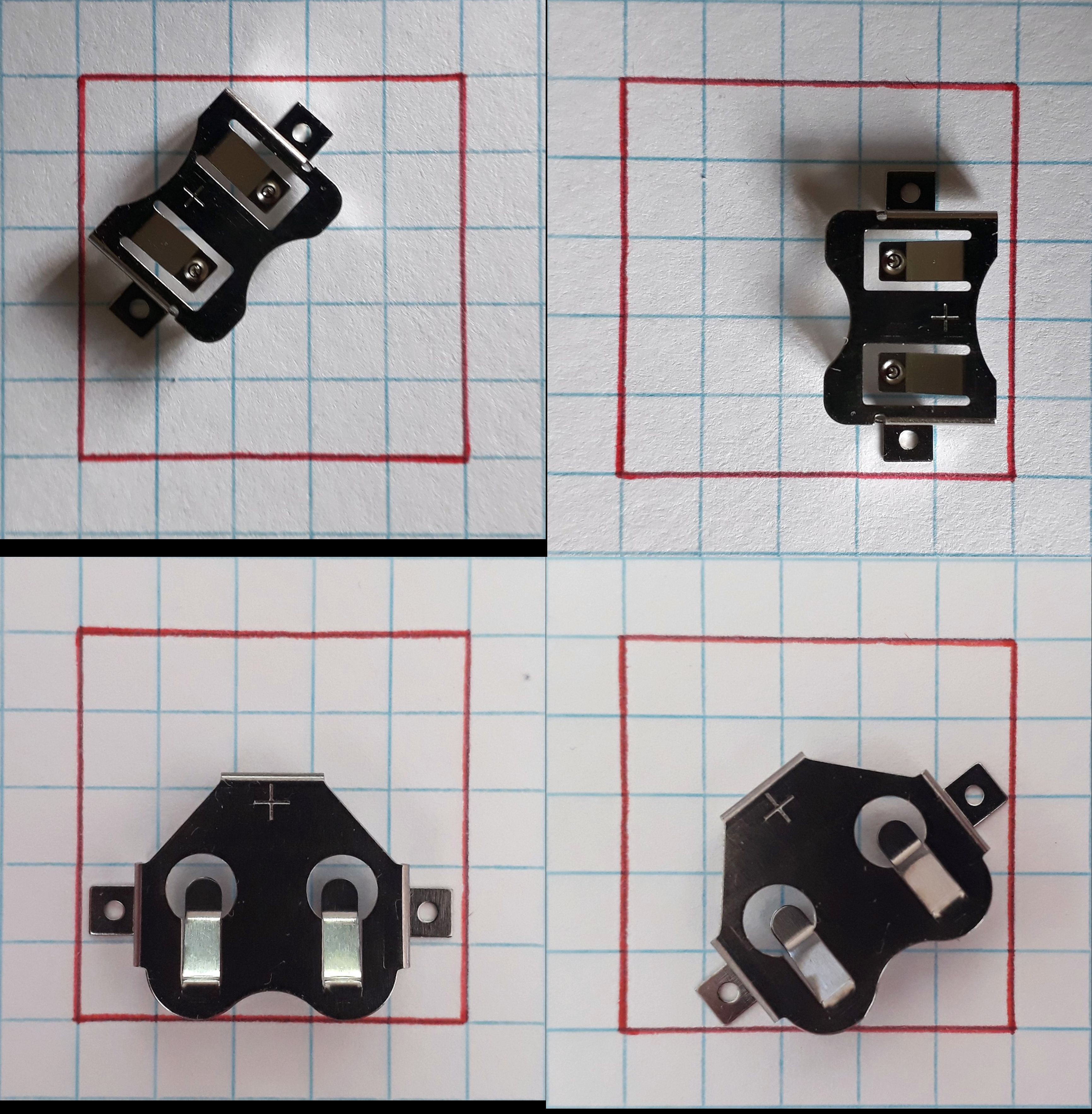
coin cell holder placements The coin cell holder will take much of the PCB bottom side. Battery needs to be easily accessed, so I can't place components where the battery is slided in. Top 2 pics are CR1225, bottom pics are CR1632. As I#ll go with the CR16xx cells, bottom left seems most space-saving.
That's it for today. Weekend is here, need to have a few beers :)
Cheers, Jan
-
01 – choice of components
08/09/2018 at 10:32 • 0 commentsThis log is all about the why, not the how...
Space is the limiting factor in this project. I've got a full top PCB pane of 25.4x25.4mm and around 1/3 of that on the bottom side to put parts on. The rest of the bottom side is occupied by the coin cell holder.
As I intend to put the PCB directly into the brood comb, I need to save as much space (especially in height) as possible.
The PCB
1,6mm is standard FR4 for most board houses. I chose 0.8mm and 2oz copper to keep the height down. Board house will be @oshpark.
Battery
There's not much to choose from here. A 2032 cell is too large and occupies the whole bottom of my board. A CR1225 fits perfectly, but has only around 48mAh capacity,
so I need to do super power saving stuff to get my 1 year of up time. I'll do my calculations with 35mAh to be safe. The battery holder will be the Renata SMTM1225 SMD coin cell holder.With my setup I expect around 380 days of run time with a sleep current of 0.003mA, 4 wake-ups per hour, each 1s long and a current consumption of 0.2mA during logging.For my calculations I like to use the Oregon Embedded Battery Life Calculator, which has proven to be quite accurate.
Edit 02.10.2018: I decided to choose CR16xx coin cells over CR12xx ones. The reason is I wanted the logger to run longer than a year (plan to let it sit in the bee hive for 2 years). This can't be done with 48mAh of battery capacity. Varta claims their CR1632 cells have 140mAh @ 0.03mA discharge rate at a cutoff voltage of 2V. The measured sleep current is 0.002mA (2µA), so I guess I can work with these values.
What I don't know yet is if the cell can handle the short power surge, when waking up from sleep and writing to the EEPROM at these voltage levels. I'll need to deplete one battery and see how it works.
The microcontroller
Atmega328P-MU, any questions? Jokes aside, I have two of them sitting in my shelf and didn't solder the small HVQN32 package yet. TIME!
It will be clocked at 1Mhz internal to keep the coin cell from draining too fast. Current consumption is expected to be around 0.2mA when running/collecting data and 0.1µA when in power down mode.
Of course the other parts will add to that but will be powered off in sleep mode anyway...
RTC
DS3231 in a 8 pin package. Easy to use, drifts a few seconds a year, easy to control + has alarms, which are essential for precise wake/sleep cycles. It uses around 0.002mA when in battery backup mode.
Note: the RTC is connected kind of "wrong" in my application. I could have connected Vcc to GND to run the RTC in battery only mode (Datasheet, Page 9). As it is powered together with all the other components from pin A2, it tries to switch all the time from Vcc to battery mode. It stops doing that when A2 turns LOW. Anyway, there's no downside to that. It works fine as it is.
Next revision will have Vcc connected to GND nonetheless, because it uses much less power in battery only mode!Memory/EEPROM
Unfortunately using an micro SD is not possible with such a weak coin cell. It would be like a short circuit drawing 100mA peak from it.
I'll go with the pretty standard 24LC512, 24LC1026 or 24M02. They all work quite the same + pinout is the same!
Temperature sensors
It really breaks my heart, but my beloved DS18B20 sensors aren't too happy working below 3V. As I don't want to use a boost converter I had to switch to other sensors. Requirements:
- accuracy of +- 0.5°C
- more than one sensor at a bus
- small package (<TO92)
A quick search on lcsc.com gave me 3 options:
- Microchip Tech MCP9808-E/MS
- size: 4.9x3mm, height 1.1mm
- accuracy 0.5°C
- 2.7V to 5.5V
- TI TMP275
- size: 3x3mm, height 1.1mm
- accuracy 0.5°C
- 2.7V to 5.5V
- TI TMP112AIDRLR
- size: 1.6x1.6mm, height 0.6mm
- accuracy 0.5°C
- 1.4V to 3.6V
I chose number 3, as it seems just solder-able by hot air (0.5mm pitch) and is super small. In a lot of 10 its under 0.8€/piece, so that's alright with me. 4 of them can be used on one bus: nice!
Power consumption is 10μA active (maximum), 1µA Shutdown (maximum). They won't need turning them on/off to save power. For external sensors I will use 0.1mm diameter enameled copper wire. Don't know yet if I solder the wires directly to the sensors or if I create small break out boards... Hope one of these methods works.
Bottom line
Those components will all fit onto my board. I'll add an LED and rest/user button as well in the final layout.
The Atmega328P-MU and TMP112 are packages I have no experience soldering so I guess I'll learn something on my way too!
micropower micrologger [mPmL]
A set-and-forget I2C/digital datalogger. Size: 25.3x 18x 10mm incl. battery. Runtime: > 1year