Close
0%
0%

Ariadne Headband

Arduino-based heaband that uses haptic feedback to navigate blind people. Controlled via Bluetooth using Android app.

Public Chat
Similar projects worth following
Ariadne Headband is ongoing project that aims to create haptic navigation for blind people (among others). It uses 4 vibration motors placed in set directions on head and connected to Arduino board. Everything is controlled with Android app via Bluetooth.


Ariadne was daughter of the ancient ruler Minos. Her duty was to oversee famous labyrinth where mythical beast Minotaur lived. One of the young people sacrificed to Minotaur was Theseus—a hero from Athens. He planned to kill the beast and save the life of others. Ariadne fell in love with him and wanted to help so he can achieve his goal. She gave Theseus ball of thread and a sword. When he entered the maze, he should unravel the thread so he can follow it on his way out of the labyrinth.

Since then the term Ariadne’s Thread means a way or a tool to find a way through unfortunate situation.

What is project Ariadne Headband?

Ariadne Headband is actively developed project that tries to provide haptic navigation for people who cannot use other ways—either they are unable to use visual navigation, do not have time for it or cannot see at all. Our main goal is to help blind people but Ariadne Headband can be useful in other cases too, e. g. runners or bikers. Our Headband can show these people direction to their selected destination, geographical North of eventually which way they should go on crossroads (work is still in progress).

How does it work?

Project Ariadne Headband is made out of two parts: headband and Android app. The common usage flow is following. First, you open Ariadne Headband app. Using this app you connect via Bluetooth to your Headband. Next, the app will ask for you current GPS location. Then you open Google Maps integrated into our app and select your destination (place where you want to go).
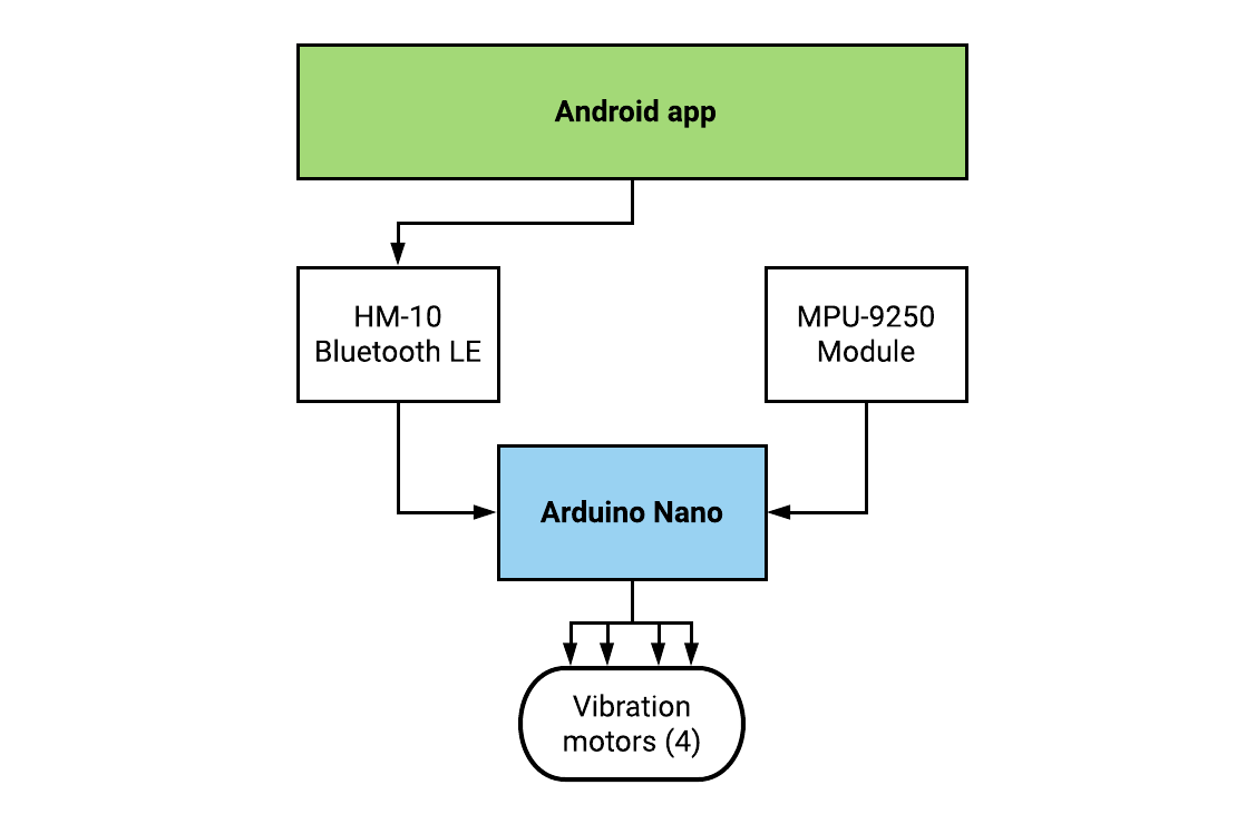
Our Android app will compute the geographical azimuth from your current location and chosen destination. When you are ready you start navigating by pressing a button that sends computed azimuth to the Headband you put on your head. Azimuth plus some other data are sent as a bytearray through Bluetooth Low Energy.

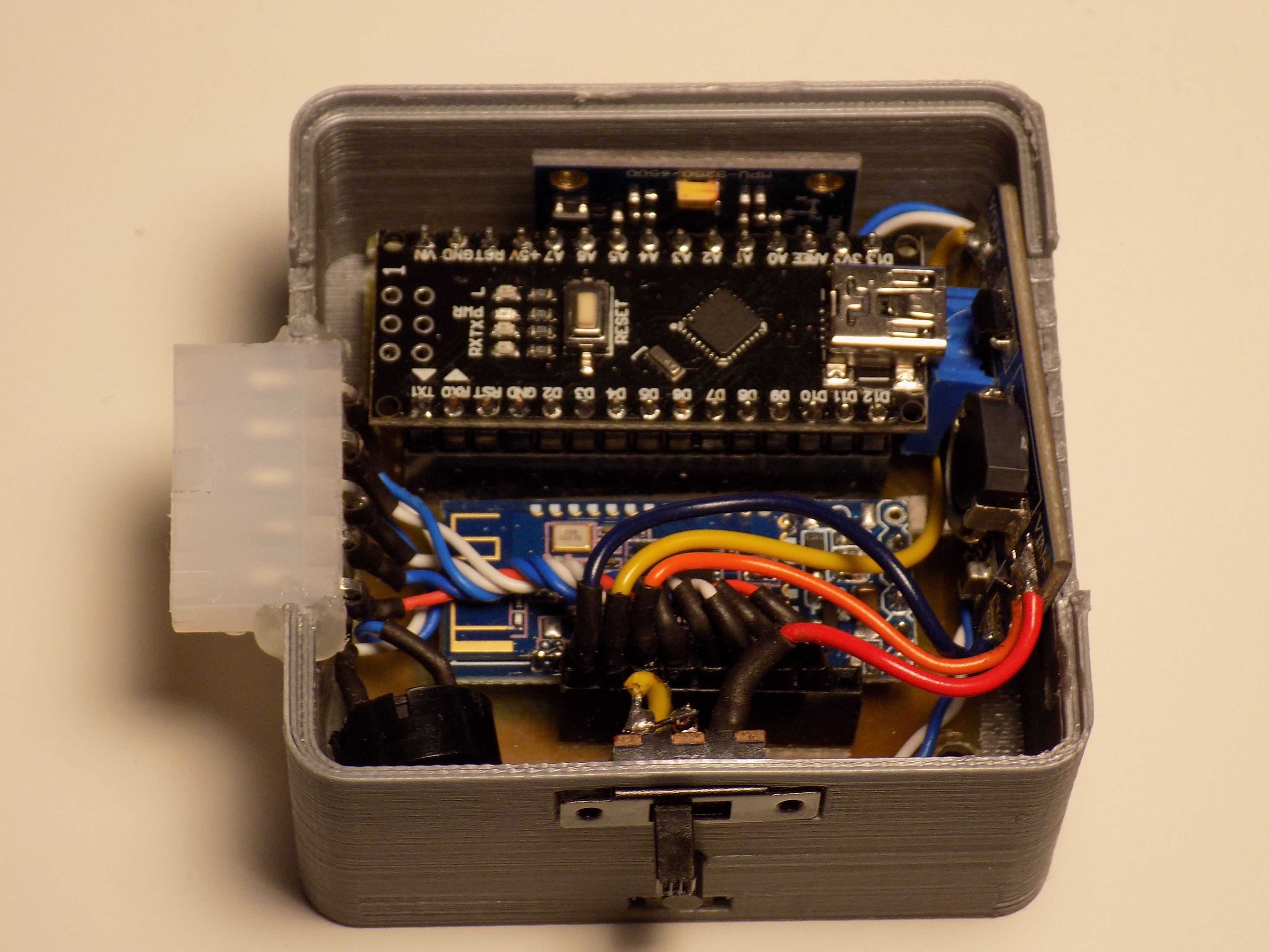
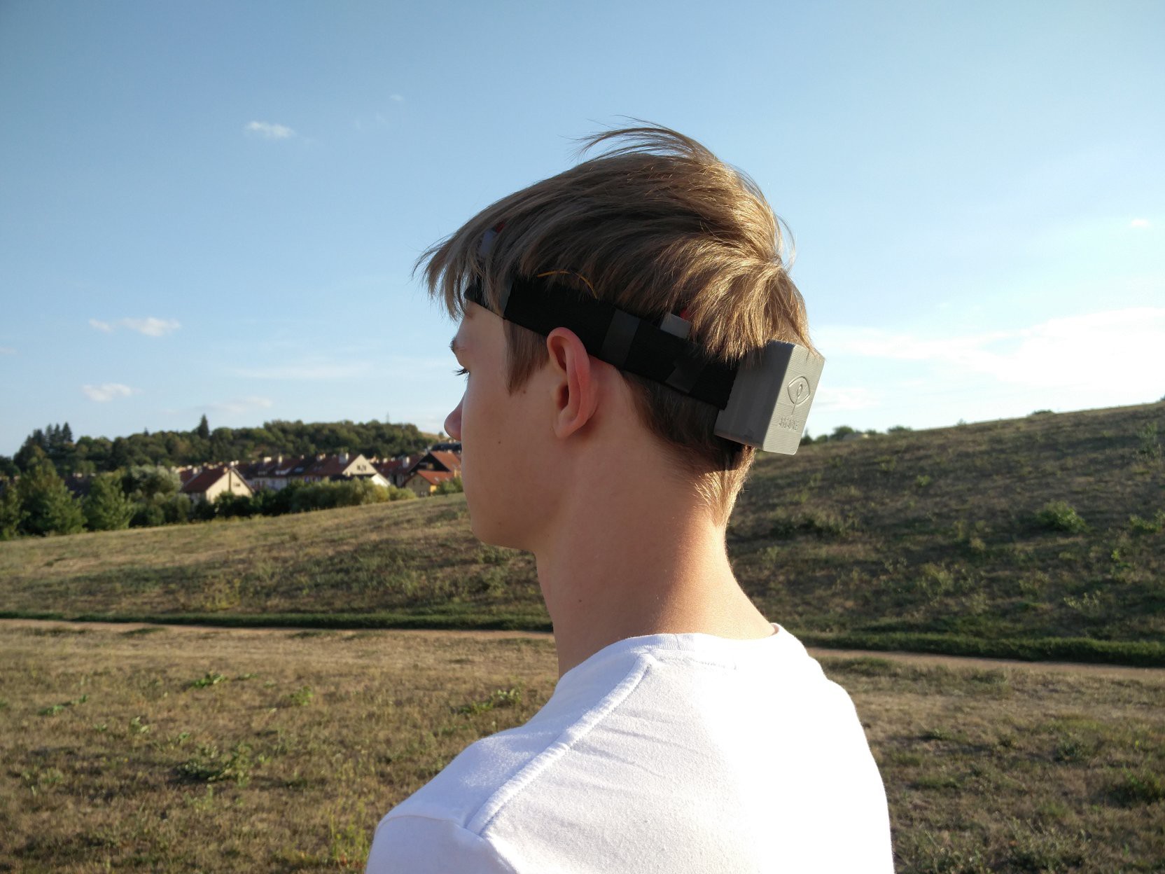
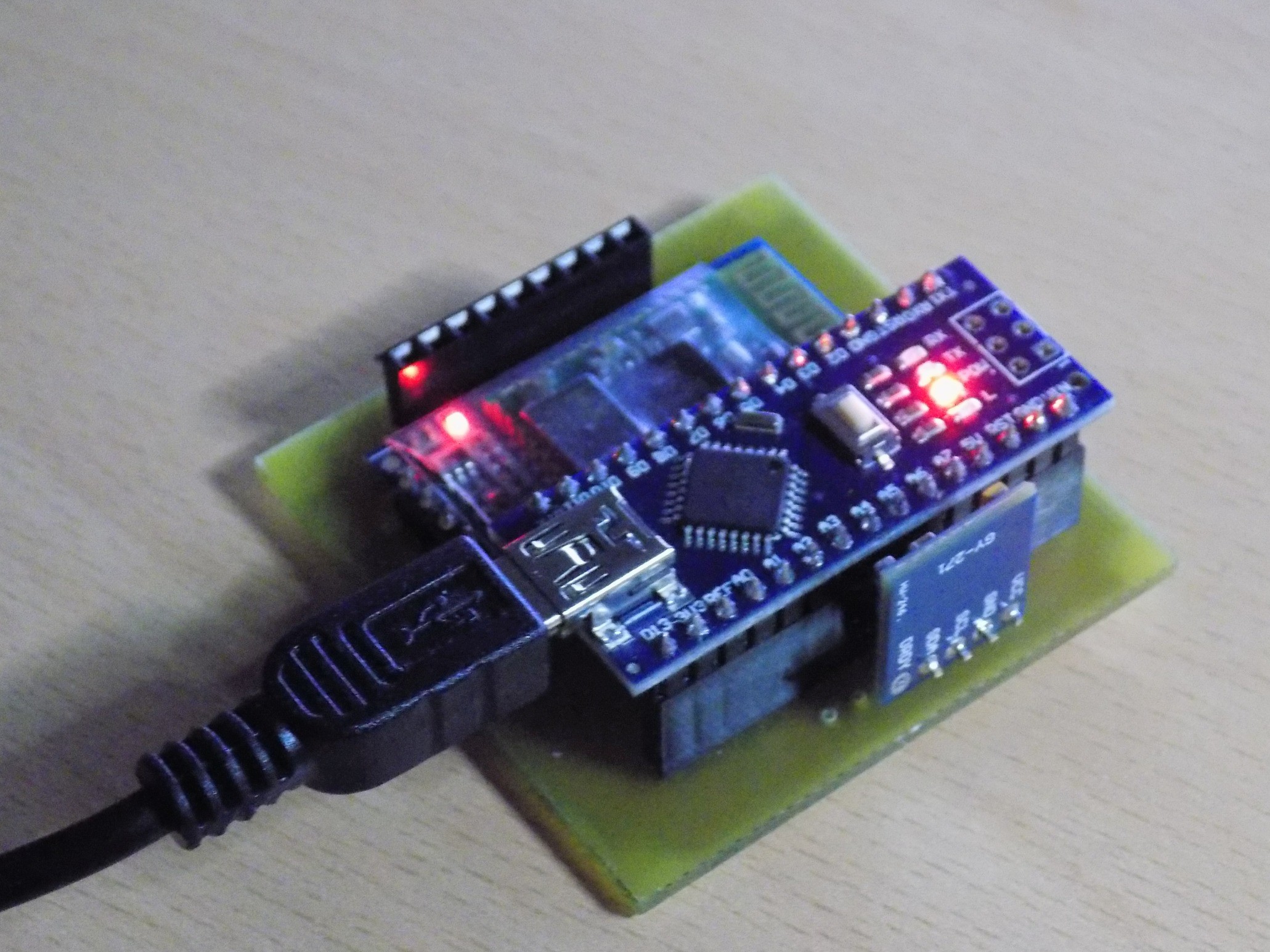
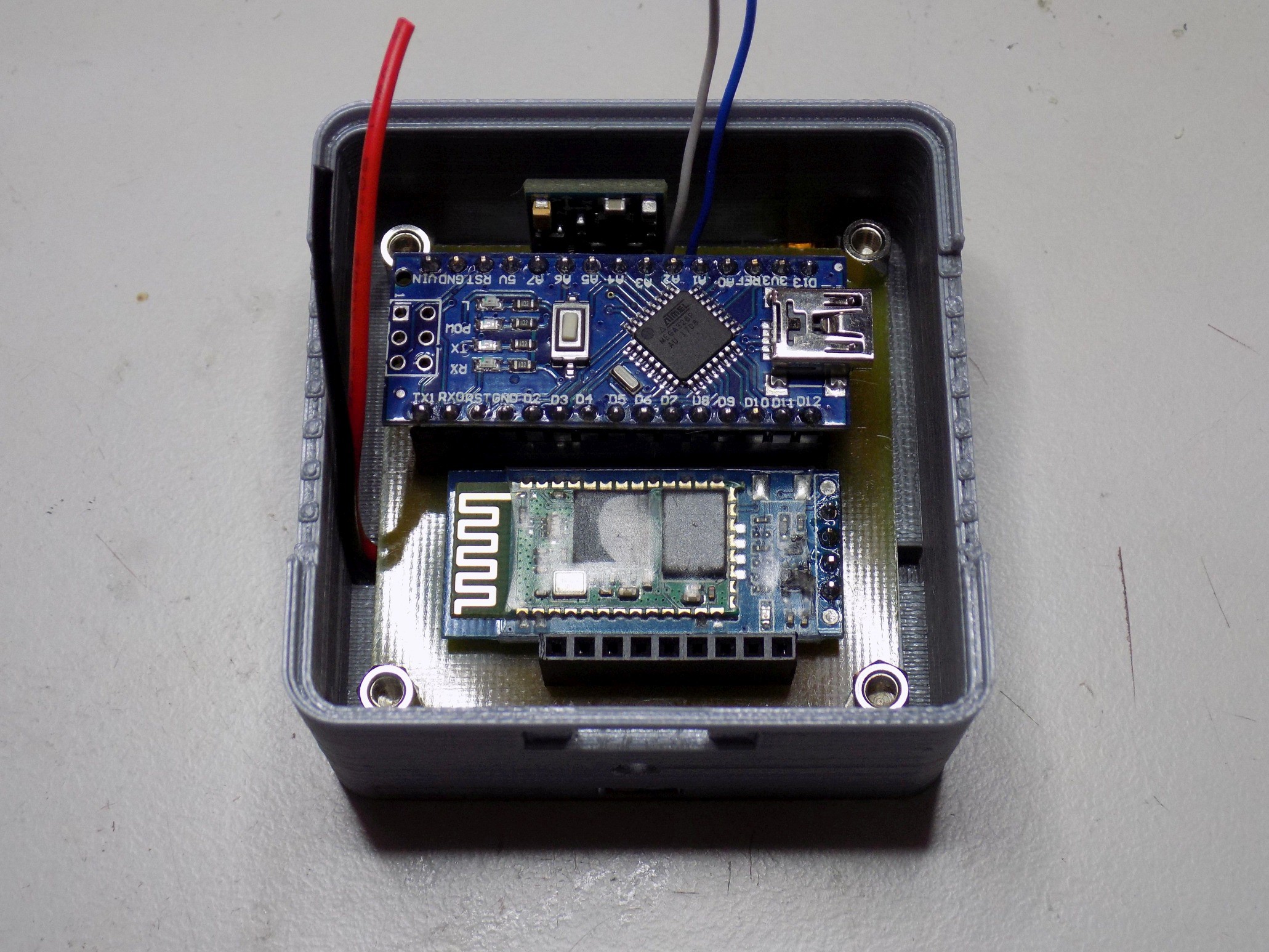
Headband consists of Arduino Nano board,  MPU-9250 "compass" module, HM-10 Bluetooth Low Energy module and 4 vibration motors. Compass module allows us to know current azimuth, that is where is the user looking. All components are placed into a box on back of your head. Our aim in the future will be to make this as small as possible so you will not even feel it. It is also possible to place everything into a hat or helmet for example instead of rubber headband. We are using rubber headband because it is very easy to manipulate. 

Vibration motors around your head are placed in set directions so they can signalize where you should head. Your heading is computed by taking your current azimuth and the azimuth sent from android app (that is where you are currently going and where you should go, respectively). See illustration below for Headband overview.

For example, Motor 1 is activated when you should head 45° (this is same for other diagonal directions). If you should head straight, both Motor 4 and Motor 1 will be activated. The similar approach applies for left, right and turn back signals. We originally planned to use 8 vibration motors, one for every 45° but have concluded that it would by more complicated and would not be worth it. The motors would be too close together and it would be hard to recognize right direction. Using 4 vibration motors is both cheaper and more robust.

Why is is useful?

As you might seen in a MythBusters scene or in few videos on YouTube, it is hard to walk straight when you cannot see. Blind people who use cane have to find some guideline, pavement for example, or use guiding dog. Otherwise it is not easy for them to keep right direction. For the other cases, some people like runners usually do not want to stop and look on their phone where they should head.

... Read more »

ariadne-schematic.png

Portable Network Graphics (PNG) - 34.78 kB - 10/22/2018 at 11:47

Preview

ariadne-gerber.zip

Gerber files

x-zip-compressed - 15.33 kB - 10/21/2018 at 18:52

Download

ariadne-place.png

Portable Network Graphics (PNG) - 44.38 kB - 08/26/2018 at 17:42

Preview

ariadne-pcb.png

Portable Network Graphics (PNG) - 35.32 kB - 08/26/2018 at 17:42

Preview

ariadne-box-bottom.STL

Standard Tesselated Geometry - 157.60 kB - 08/24/2018 at 15:19

Download

View all 7 files

  • 1 × Arduino Nano
  • 1 × HM-10 Bluetooth Low Energy Module
  • 1 × 03962A Lithium Battery Charger Module
  • 1 × MT3608 Step-Up Converter
  • 1 × MPU-9250 Module

View all 24 components

  • New Beginnings And New Hardware

    Vojtech Pavlovsky08/26/2019 at 18:23 0 comments

    Hello everybody! We are still alive!

    It is a while since we published our last update. We are extremely grateful for everybody who follow this project and is interested in our progress. Thank you all for your patience.

    We are finally ready to resume our work. At the right time.

    Hardware

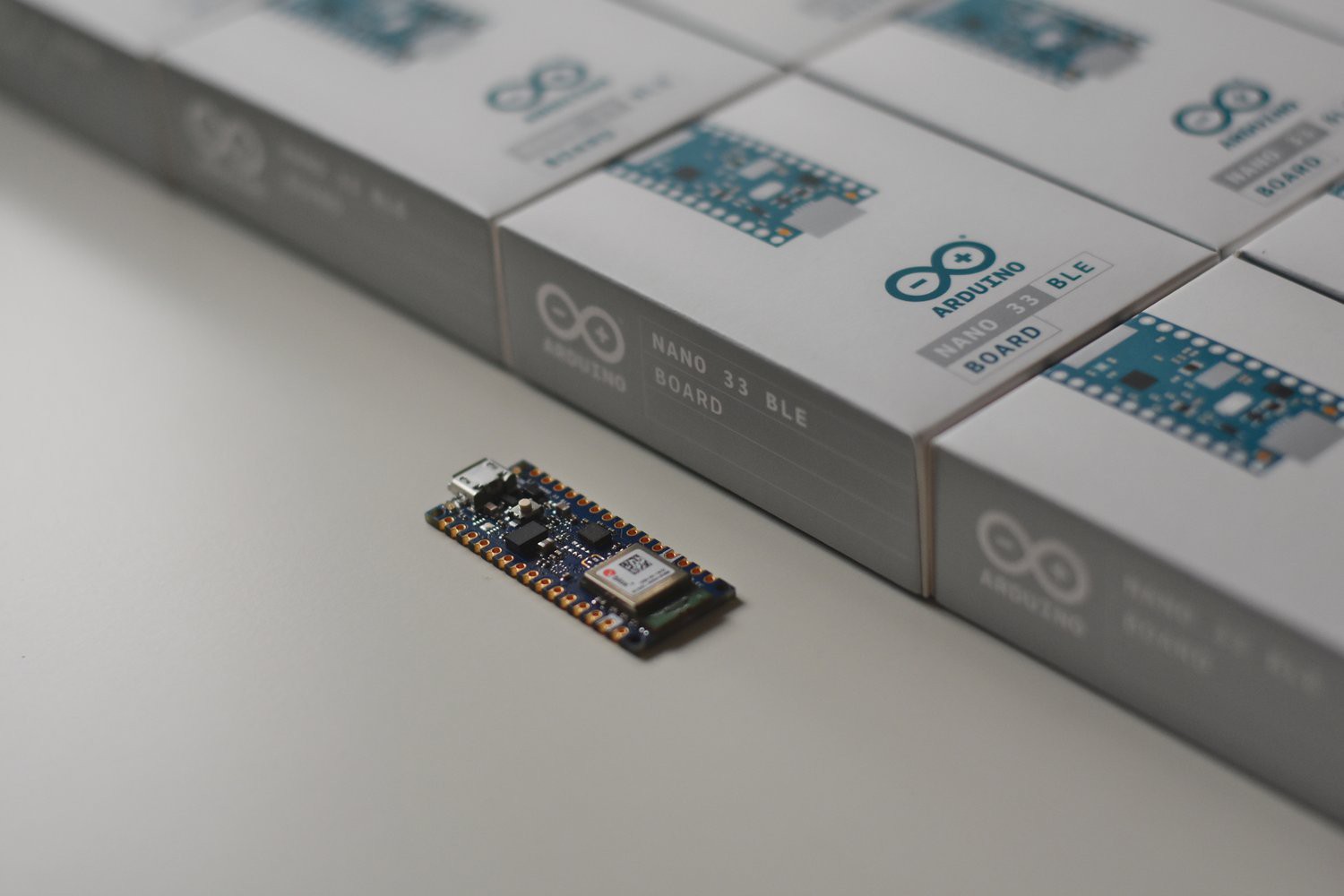
    Arduino is shipping brand new Arduino Nano 33 BLE since this month. It is extremely interesting development board that exactly fits our needs. It has powerful ARM processor, Bluetooth 5.0 module and IMU (containing gyroscope, accelerometer, and magnetometer). A god send.

    This board allow us to make our headband extremely small because every part is already included on board. All while keeping the price still the same, maybe even lower. The new Nano costs only 20 USD.

    It is so good we have bought a several of them!

    Arduino Nano 33 BLE
    Our Arduino Nano 33 BLE

    Software

    We are researching new routing services. Google Maps SDK will not allow our use case because of their usage terms. Also, their pricing has recently steeply increased so it is not really suitable for small open-source projects.

    We have found Graphhopper, which is a open-source routing service. Their terms and conditions are way better. We are currently using their free tier, but it is possible to host your own server. Almost perfect for projects like our. They use OpenStreetMaps, so we can build on nice open-source stack.


    Thanks for your support!

  • Sewing the Headband!

    Vojtech Pavlovsky10/21/2018 at 16:42 0 comments

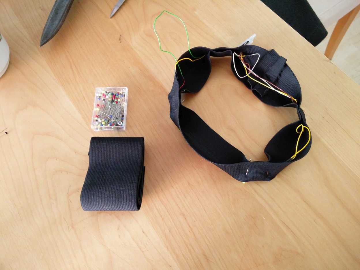
    As you might read in previous log, hardware was not the only thing that changed since the last version of Ariadne Headband. We have also completely reworked the rubber headband that contains vibrations motors. Now, it is finally without that super fancy duct-tape. It is also smaller and more durable.

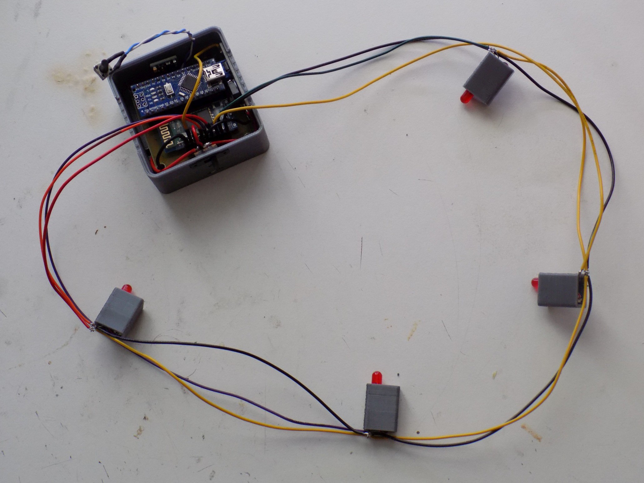
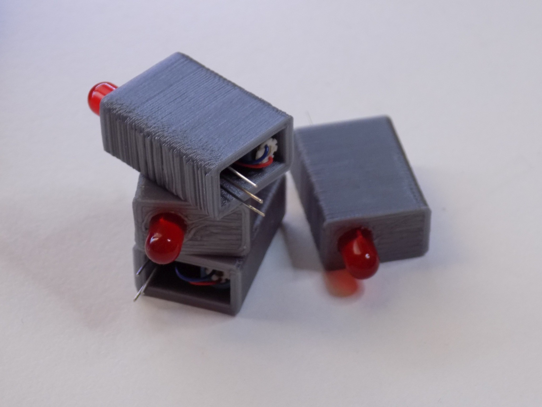
    In first version of Ariadne Headband, we have used cylindrical vibration motors covered with plastic boxing and connected to LED. This solution was nice for testing, because we could easily see which motors are activated at the moment.

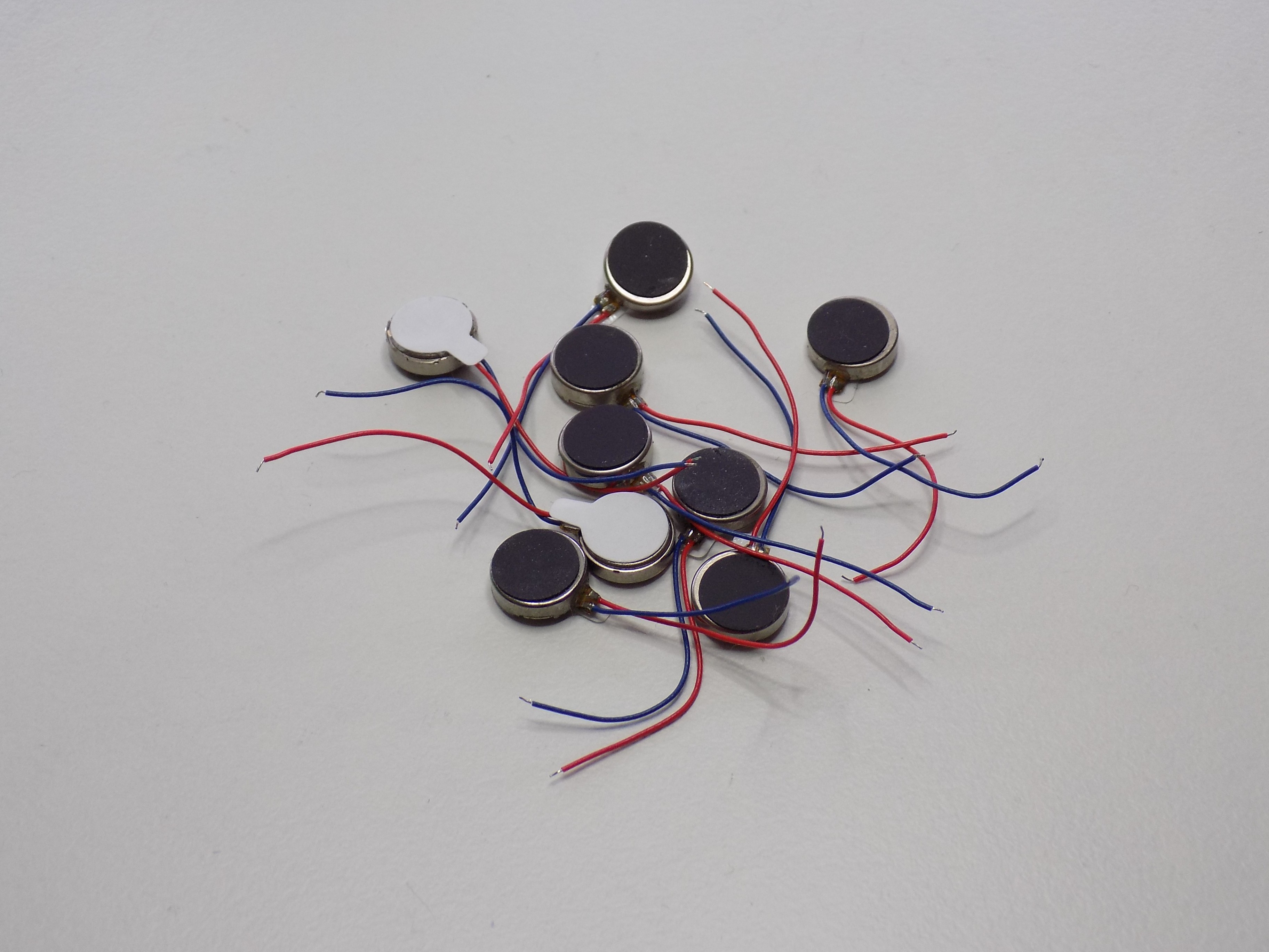
    But with new flat vibration motors we have completely got rid of plastic boxing with LED and now there is only the vibration motor sewed directly to the rubber headband. We do everything by hand and this part is not an exception.

    This way, the motors are in almost direct contact with head of the user so they can easily feel which way they should head. Cables are very loosely inside the rubber so they can stretch when needed and nothing will tear.

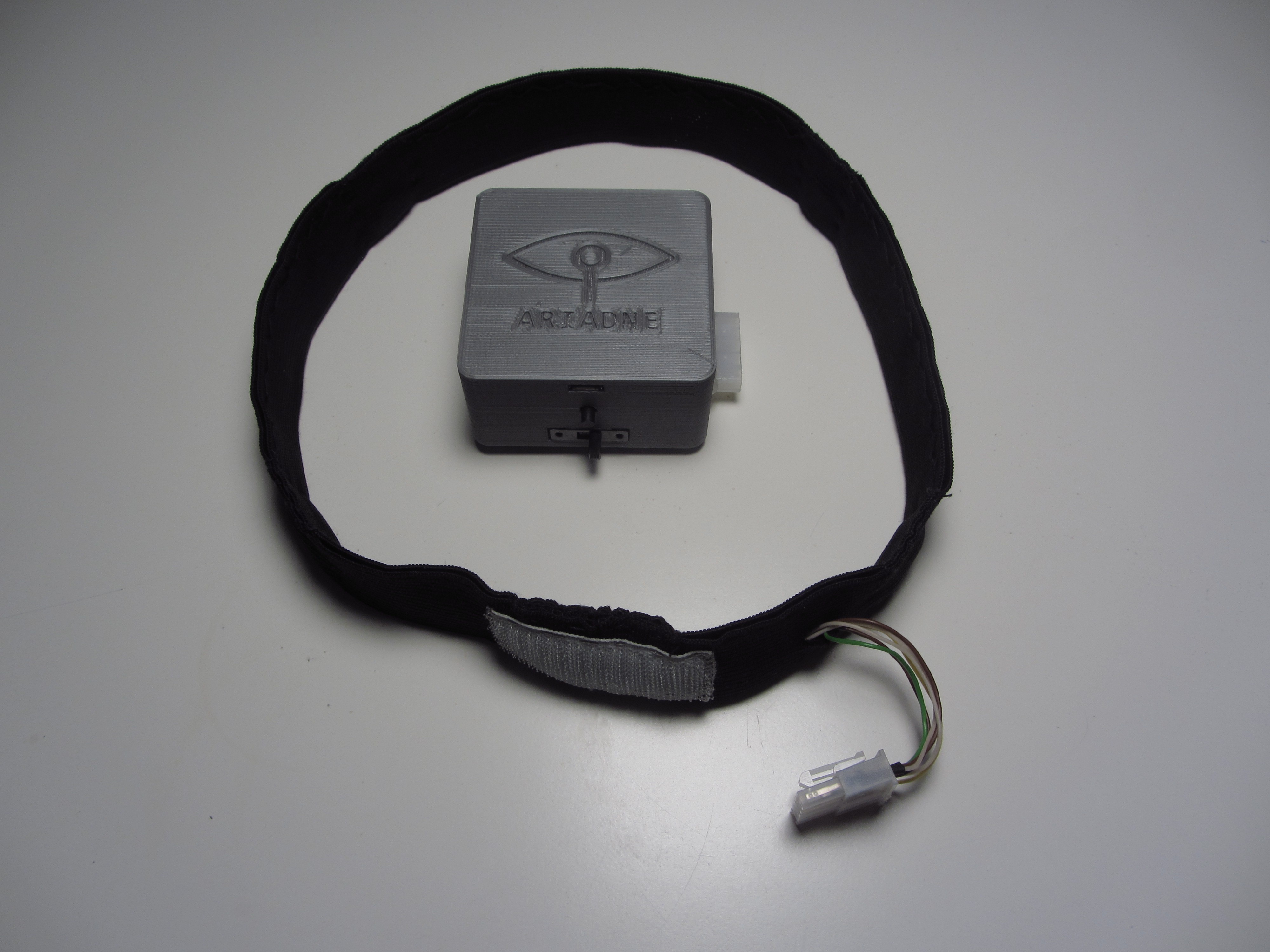
    New headband was also necessary because we have decided to separate the case for electronics and the rubber headband. This makes Ariadne Headband modular. You can for example have only one Ariadne Headband case and connect it to multiple wearables. You might use a beanie hat in a winter or a cap when the sun shines. Simply uplug the cables and connect something different.

  • Upgrading Hardware

    Tomas Kosicek10/21/2018 at 15:24 0 comments

    After putting together first version of Ariadne Headband and successfully testing it we were pleased how well it worked but as it is with every first prototype it was far from perfect. When we have shown our first version to Daniel he pointed out few things. Namely that he would appreciate some kind of buzzer signalizing when the headband is turned on. He also mentioned that he would like to be able to turn off navigation by pressing button rather than turning it off automatically when you are turned the right direction.

    We took note of his remarks and revised our first prototype. We have added a piezo buzzer between arduino’s pin number five and ground. It plays simple melody when headband is turning on. We have added function to push-button which was already present. When you press the push-button while vibration motors are active you turn them off if vibration motors are inactive it turns them on. It added interesting side effect if you haven’t sent coordinates to headband yet and pressed the push-button the headband starts navigate you to the north.

    Other change was remaking the headband containing vibration motors. We have replaced original vibration motors with LEDs in 3D printed housings with flat, coin like vibration motors which you can see in the picture above and mainly adding a connector to it. So now you can separate box with electronics and headband and instead of it connect for example hat in winter or cap containing vibration motors. On the back of the electronics box and headband are Velcro fasteners for quick and easy attaching desired wearable.

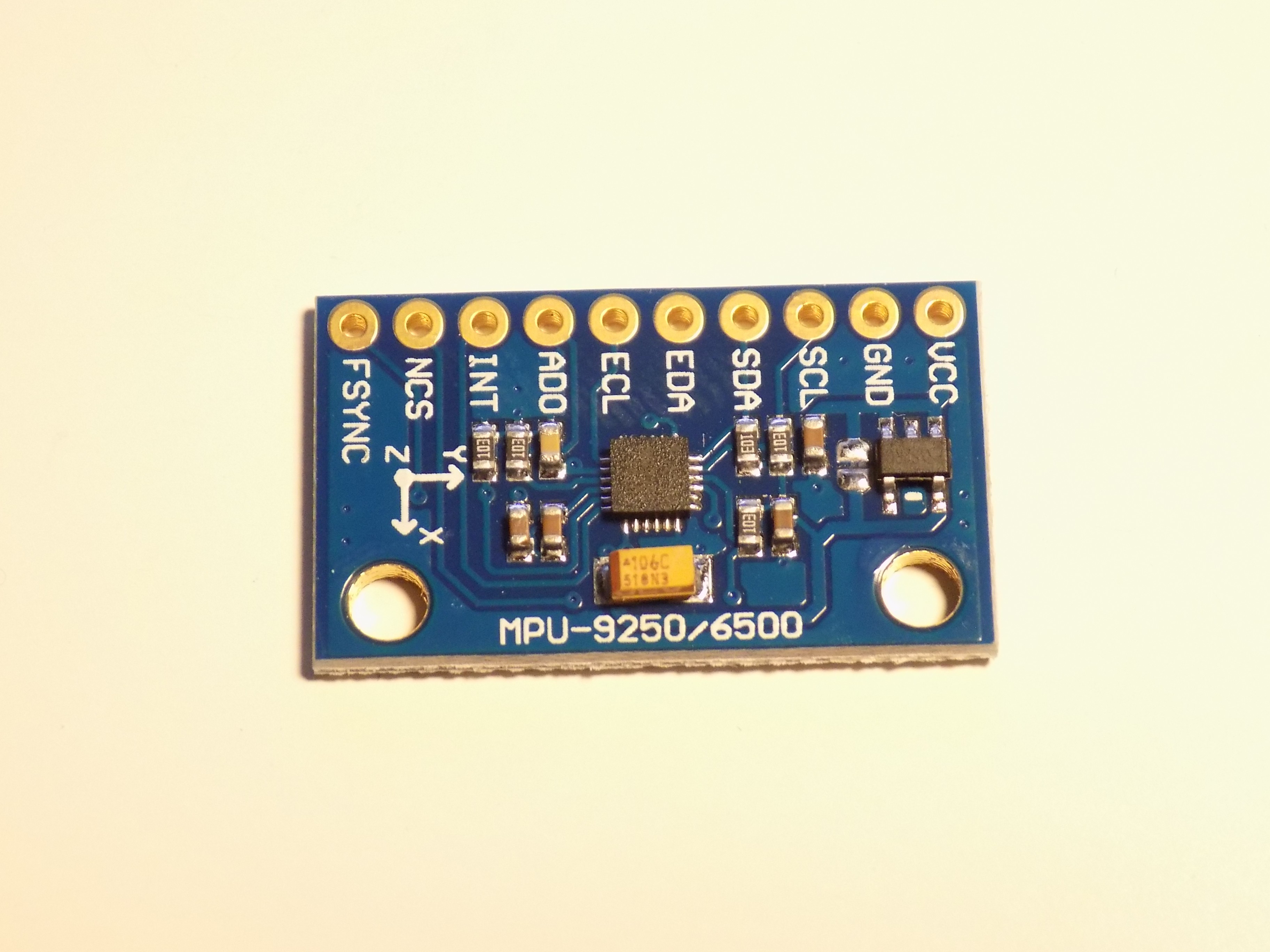
    We have also switched HC-06 bluetooth module for HM-10 bluetooth low energy module to lower power consumption and increase battery life. This required no changes in arduino’s software just swapping modules on PCB. Bluetooth wasn’t the only module we’ve changed we have also swapped GY-271 compass module for MPU-9250 which is three-axis compass, accelerometer and gyroscope in one module. Combination of compass and accelerometer should allow us to alter compass data in such way it would compensate any tilt of the device and give accurate reading of the azimuth even when tilted. You can see MPU-9250 in the image below.

    In hardware switching compass modules was pretty easy. Although MPU-9250 has more than twice as much pins as GY-271 we only use power and I2C pins which are placed in the same order on both modules. So it was just desoldering one module and soldering back the other instead. In software we had to change I2C addresses, in MPU-9250 accelerometer and gyroscope are one unit and compass other and each has its own I2C address.

    We have received MPU-9250 not a long time ago and time being scarce commodity nowadays means we weren’t able to fully utilize its abilities yet. Right now the new compass modules does the exact thing as the old one. However we are working on being able to compensate tilt of the compass a thus increasing its accuracy.

  • Testing Ariadne Headband with our blind friend

    Vojtech Pavlovsky10/21/2018 at 14:40 0 comments

    From the very beginning, our goal was to find a solution to existing problem, rather than create fancy new problem. We want to create a tool blind person would find useful. We want to make something worthy that could improve someone’s life.

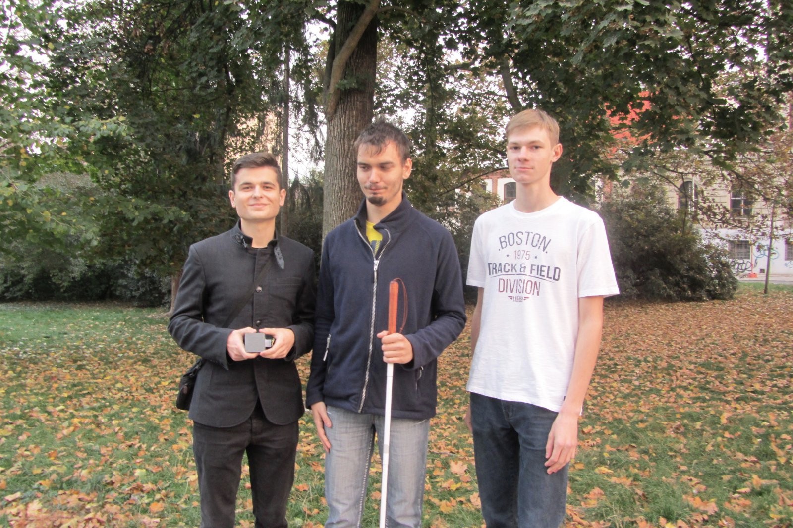
    Because of this, we have worked closely with Daniel, who is blind from his birth, and who we met while working on Ariadne Headband. Daniel tests our prototypes of Ariadne Headband and gives us feedback on what we could improve. His opinions are very important for us, because Ariadne Headband should in future serve people like him. There are, simply said, some problems we would not even think of.

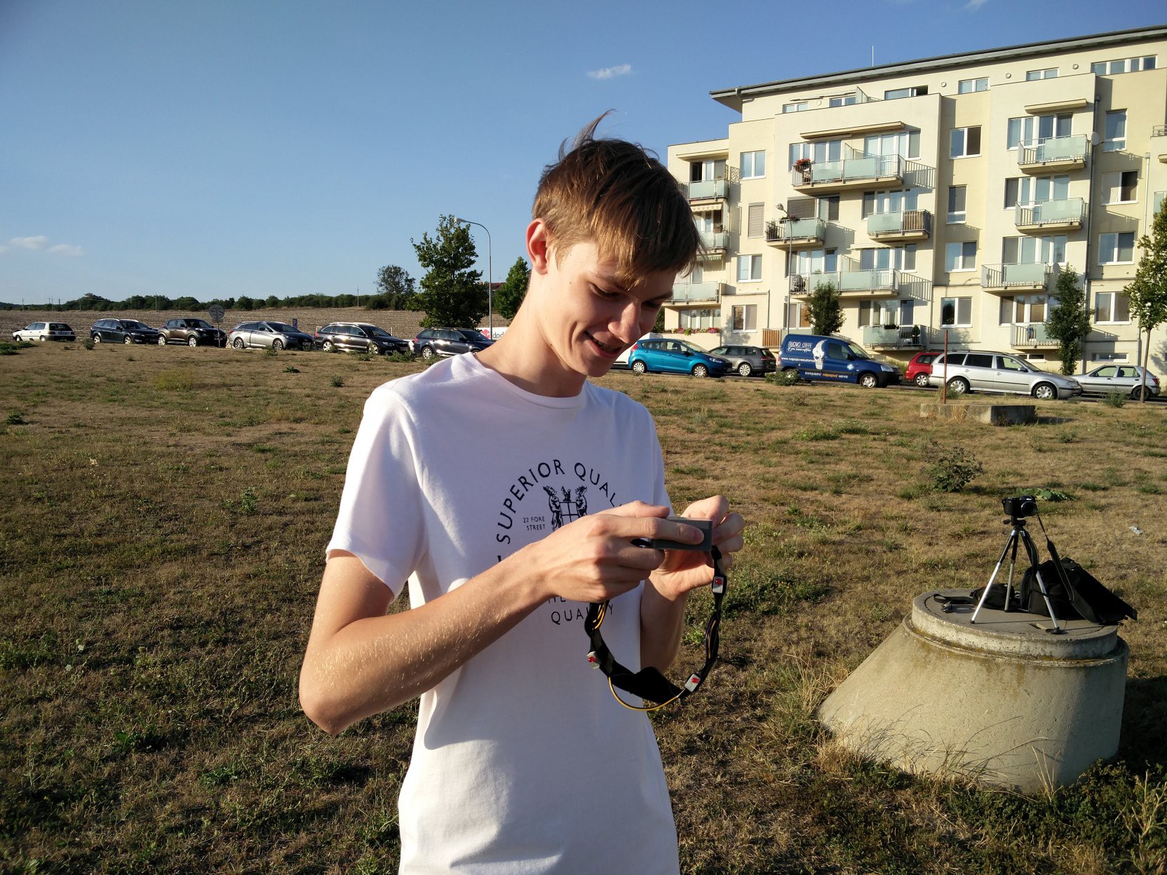
    While Daniel tested how Headband works and we often exchanged our opinions, we have not yet made “in-the-wild” test with him. So this week, we have decided to go to the park together to show him second version of Ariadne Headband and let him try it.

    We firstly made a short guide how to use our Android app, mainly Bookmarked locations because they were added recently and Daniel did not tried them before. Then we presented him the new version of Ariadne and described things we changed. New version uses more suitable vibration motors and, what is very important, is now modular. That means you can unplug the gray box from the rubber headband and connect it into different wearable, like a hat in winter. We will take a look on this change in different log.

    As it is with every product presentation, everything that can break, will break. We had some problems that appeared just before the testing, so Tomas had to take his laptop and fix them right in the park, while Daniel patiently waited. He was very interested in testing Ariadne Headband, because he is very supportive of what we do so he did not really mind. It was just slightly embarrassing.

    We have fixed the issues eventually and Daniel was free to test Ariadne Headband. It was nice to see someone else try our device. Nice way to spend a day!

  • Making our app accessible to blind users

    Vojtech Pavlovsky10/21/2018 at 14:37 0 comments

    You might wonder: if we are making navigation for blind people that is controlled by smartphone, how will they possibly control it when they cannot see what is on the screen? Our serious concern is to make our app eventually fully accessible without needing to touch anything. But this feature is still just on our roadmap. In this post I would like to take a quick view on ways visually impaired people can use their smartphones and what we do in our app to make it easier for them.

    TalkBack and VoiceOver

    Almost every modern smartphone has some sort of accessibility app. For Android there is Google’s TalkBack and on iOS it is VoiceOver. These apps are usually installed as a system app on most phones so you do not need to install it – simply turn in on in settings (though when you do not know how to control it, you will have hard times turning it off…). I use custom ROM on my phone so I had to install TalkBack from Play Store manually to my phone.

    When you turn on TalkBack functionality, it will fully change the way you can use your phone. As a regular user you can use eyes to see what is on your screen right now, read text and click buttons. When TalkBack is on, your phone will read aloud elements on the screen. It will start at the top and continue to the bottom, from left to right. You can switch to the following element with swiping anywhere on the screen, and the focus of reader will go to it. You can cycle through whole app while the you can hear what button (or other element) you are focused right now. If you want to interact, simply double tap on the screen.

    But does it really work?

    We finally realized how important TalkBack is when we handed a phone with Ariadne app to our friend Daniel, who is blind from his birth. When we had first working prototype, we wanted to show it to someone, who could judge whether was our project useful. I studied how TalkBack works the night before so I could be prepared. In his hands, using Ariadne app with TalkBack seemed way easier and fluent than I hoped for. (So good that he wanted his own piece of Ariadne Headband as soon as possible!)

    Not everything was finished at that time though. Since then we have polished the usability a bit more. For example, if there is a button that has only icon and not text, it is important to add a Accessibility Description attribute so TalkBack know how to properly read it. It is also very useful to group similar control elements together and also logically structure them so blind users can easily understand the control flow.

    In the first version of our app it was only possible to select destination on a map. While TalkBack can do miracles, properly reading maps to someone who cannot see is not one of them. To solve this problem we have added a function to save some destinations to your bookmarks so you do not have to use map all the time. Simply add your Home as a bookmarked destination and then tap on it whenever you are. Plus, if they need to go to place that they do not have saved, they can search location by name. TalkBack even allows you to use keyboard.

  • Switching to Bluetooth Low Energy

    Vojtech Pavlovsky10/15/2018 at 16:45 0 comments

    Since the beginning of our project we have used HC-06 Bluetooth module. This component is based on Bluetooth Classic – a kind of older version of Bluetooth protocol. When you use Bluetooth Classic and connect two devices, a communication channel will be created between them so they can send data to each other. There is only one channel and it is kept open when you are connected. This is very useful when you want to send huge amount of data through it, e. g. sound (like wireless speakers). Keeping connection active at all times means that it will also drain battery a lot (at all times).

    For this reason a new version of Bluetooth protocol was designed: Bluetooth Low Energy or simply BLE (fun fact: in Czech the word “ble” is almost exactly the sound a child make when he doesn’t like food and spits it out). BLE uses so called characteristics instead of single channel. Image characteristics as a row in a data table. Each has its name or more exactly unique identificator (UUID) and some value placeholder. You can either READ characteristic or WRITE some data you want into it. Very useful is also NOTIFY function which will listen and notify you when given characteristic’s data was changed.

    BLE is often used in fitness wearables. These type of devices often track multiple health informations, be it temperature, heart rate, how many meters have you walked and more. Sending all this individual data together would be cumbersome and not very pretty. You might make a byte array and fit every possible data into it (method we use and describe lower why) and send it. But BLE offers far better way.

    You instead write different values to different characteristics on our device that collects it. Then on the mobile phone you simply can read different characteristics and put them into different variables. Fine thing about this is that you can listen for changes on specific characteristics (like heart rate and notify the user that they should calm down) or on the other side completely ignore some values you do not need. So instead of listening to everything that is sent to you as is true in the case of Bluetooth Classic, on BLE you have way more granular control over what data you really want to read from the device and also when you want to read it. This also allows you to improve battery life, sometimes significantly.

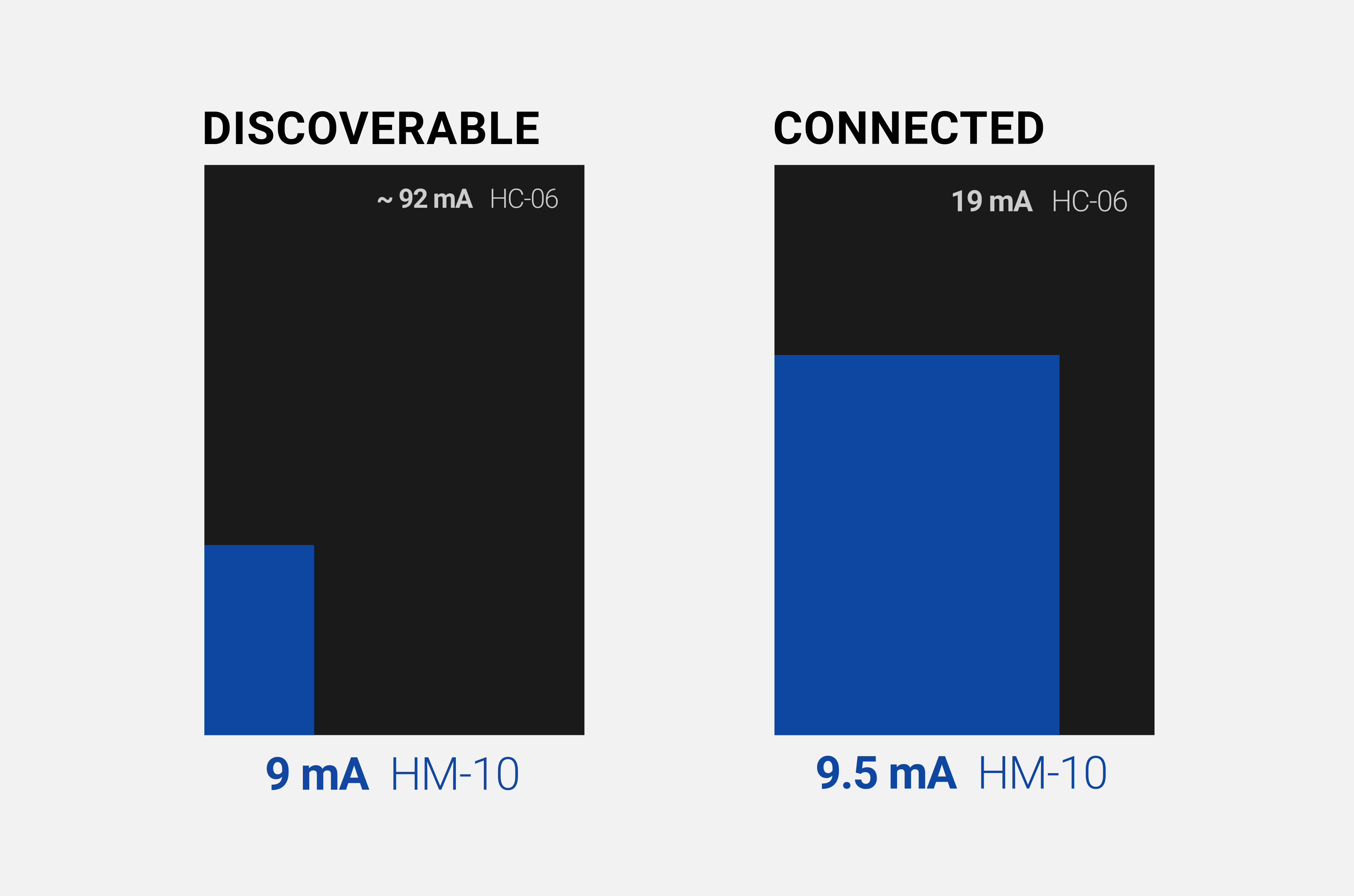
    We have HC-06 Bluetooth Classic and HM-10 Bluetooth Low energy modules in our testing. To illustrate you how drastically different power consumption can be, take a look on a graph we have created. When the module is not connected to anything, it is looking for new connection and is discoverable. During this phase, HC-06 energy consumption can vary up to 200 mA, though the average is 92 mA. HM-10 is significantly lower: it consumes only about 9 mA. When the module is connected to other device (mobile phone in our case), using BLE can save up to 50 % of power when compared to old-school HC-06.

    HM-10 Module

    We have bought a HM-10 BLE module for purpose of testing Bluetooth Low Energy. It is one of the cheapest available BLE module (mainly because of the plethora of its clones).

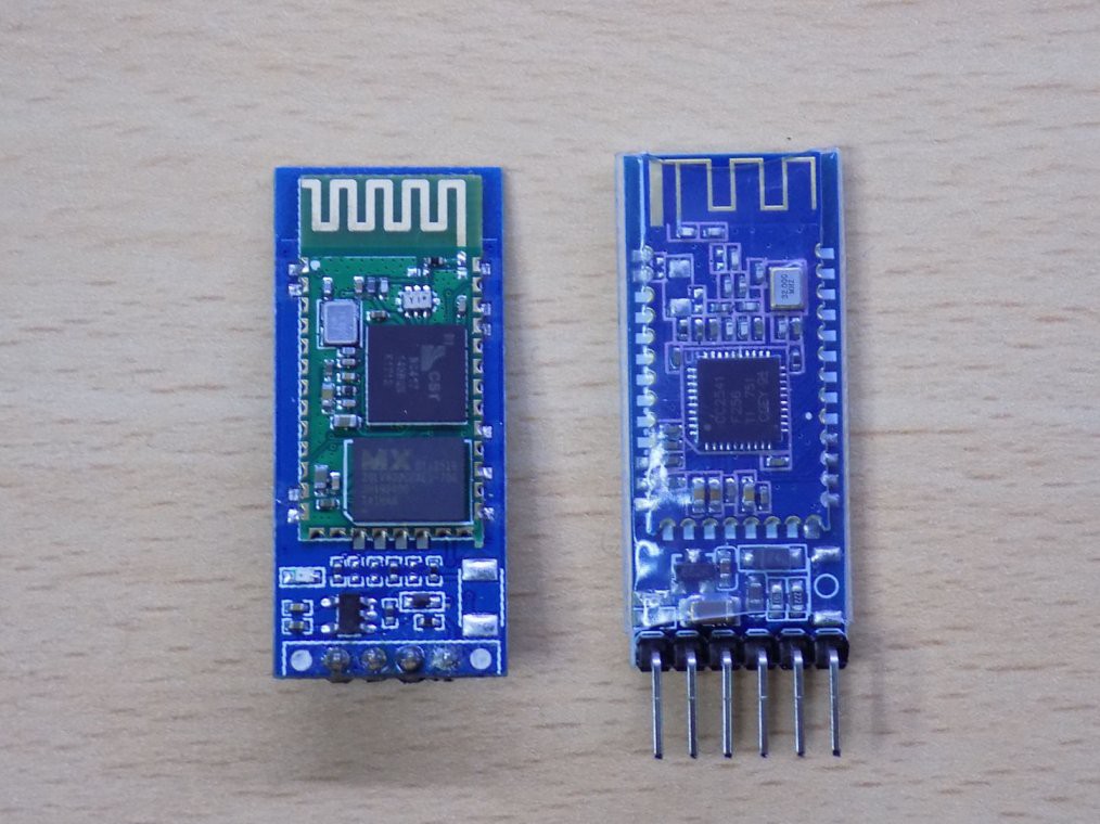
    In the picture above, you can see HC-06 module (left) and HM-10 module (right). They look almost identical.

    There is one (kind of funny) thing to note. While BLE uses characteristics instead of single communication channel. But there is a catch with HM-10: it has only one available characteristic that you can write to. Anything written to this characteristic will be immediately sent to Arduino’s serial port and vice versa. This means that while HM-10 is BLE it pretty much acts like a standard Bluetooth Classic module.

    We are planning to find better BLE module to put into Ariadne Headband. BLE protocol is incompatible with Bluetooth Classic so we had to change our Android’s...

    Read more »

  • Updating App's GPS Location Usage

    Vojtech Pavlovsky09/18/2018 at 19:18 0 comments

    Hello fellow hackers! We want to say that we are extremely happy that we can be part of Hackaday Prize 2018. It warms our hearts knowing that people are interested in our project and are even willing to like us or follow us. With many new bought hardware upgrades on way to us, I decided to begin new work on our open-sourced Android app in the meanwhile.

    Until now, Ariadne Headband app would query user’s location only when he opened map and tried to select destination. This was suitable for early stages of development, because we did not need to keep GPS active. You would simply select destination, wait until the app would find your location and press Start navigating. App would send the azimuth to the headband and you could go.

    However, this approach is not very good when you move. While selected destination is static, your location will change. This means that azimuth can change too. So it was time to implement location tracking to keep the azimuth updated wherever you go. This change will also move us closer to the real-time navigation that will also need to track your position while you move.

    I added Location Service file that keeps an eye on your location. Right now, the Location Service is started right on app startup. This is because getting your accurate GPS location can take a unpleasant while. From my testing it can vary between 5 seconds to even 2 minutes and it heavily depends where you are (building or under clear sky) and also when you last used location on your phone. While Android has a feature to use last known location that can shorten up this time for first pinpointing, it will reset each time you turn GPS off and on.

    From the technical perspective, we are using FusedLocationProviderClient library. That is official Google’s Android library that should be used over Android’s native GPS location library. Instead of choosing which way you want to get your location (GPS vs Network) you will choose between different levels of accuracy. FLPC will then combine multiple location sources and try to get best available location while optimizing battery usage. For our purposes we use HIGH ACCURACY mode so most of the time, app will use mainly GPS. Precision depends on your phone but is somewhere around few meters.

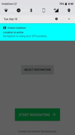
    It is also worth noting that we use Foreground service to track user’s location. This is special type of Android class that will keep running even when you switch app or lock your phone. So you can start navigation and put phone into pocket and will still keep your location updated. Foreground service requires to show a system notification so user know some process is running on background, because it will probably consume battery life. You can see the fancy notification on screenshot below.

    We are using only phone GPS module because we think that they are on par with dedicated ones you can buy. It will also lower the price of Ariadne Headband because most of the people already own a smartphone.

    I have a lot more improvements planned for our app. New school has just started for me and Tomas so we try to work hard in our free time to make project Ariadne Headband even better. Even though having less time for this project than before, we are now determined more than ever to make Headband fully working and operational. We hope that our project might once help those who are not so fortunate as we are. Or everyone who could possible find a good use of Ariadne Headband.

  • First Real-world Testing

    Vojtech Pavlovsky08/26/2018 at 21:37 0 comments

    With our first working prototype laying on desk in front of us, we decided to go out and do real-world testing. Currently, Ariadne Headband works as follow: you select a destination on your phone, customize vibration motors intensity and press start button. From that moment, motors on Headband will be activated, each time the proper ones that are in the direction where your should look. The motors will be vibrating until you look in the right direction. Then they will turn off until you start navigation again.

    This was our first proper testing, outside of our homes. We found a best place where Ariadne Headband can be the most useful: big and empty field. From the start we quite enjoyed using it. We were happy that there was no loose cable and it worked. Boxing with components inside was designed by Tomas and is very well printed so everything stays on its place. We have yet to improve the rubber band as it was little bit tight for my larger head (Tomas was fine). For now we are holding the motors by ducktape, which is not the prettiest method. Once we choose the most universal length and width of the rubber band we plan to sew it everything together. And we will also omit the LEDs as they are mainly for effect (so we can easily see which motor is activated when it is not on our head).

    The moment of truth

    So we gave it a test. One of us put the Headband on his head and the other opened the mobile app a selected a destination close to our position. We were surprised how well it worked. The one of us with Headband on looked the right way most of the time. For the bystanders our testing may looked a little weird. But is not everything new a little weird? This first version of Ariadne Headband met our expectations. It is nice to finally turn on your project and see it work as it should.

    The only occured problems were mostly software bugs. Android GPS location was sometime stubborn and took a while to find the current location. I believe that it is due to my phone’s privacy settings and should work better on regular phones. We also plan to use Android Services for GPS tracking so we can have location updates even when you do not have maps opened. Right now, GPS is triggered only when you press Select destination and will have to be find every time again. However, when you do not move it does not matter that much, because Android remembers your last position quite accurately.

    Nevermind omnipresent programming bugs we were quite happy with results. We now know that our project is able to navigate you quite nicely. It is certain we will have to invest more time into making it more user friendly and fix troubling bugs.

    When we make it into more advanced version we would like to try it with people that could give us useful feedback. We plan to visit local association of blind people as soon as it looks and works well enough.

  • GY-271 Compass Module

    Tomas Kosicek08/26/2018 at 21:27 0 comments

    Compass module is probably the most important part of the headband. Without it we would not be able to determine azimuth and therefore navigation would be impossible. We went with GY-271 compass module mainly because it was locally available and we could get it in short time. After initial difficulties with getting data from the module we found out that module we got is equipped with QMC5883L IC instead of HMC5883L which we expected. Main difference between these two are different addresses of I2C and registers.

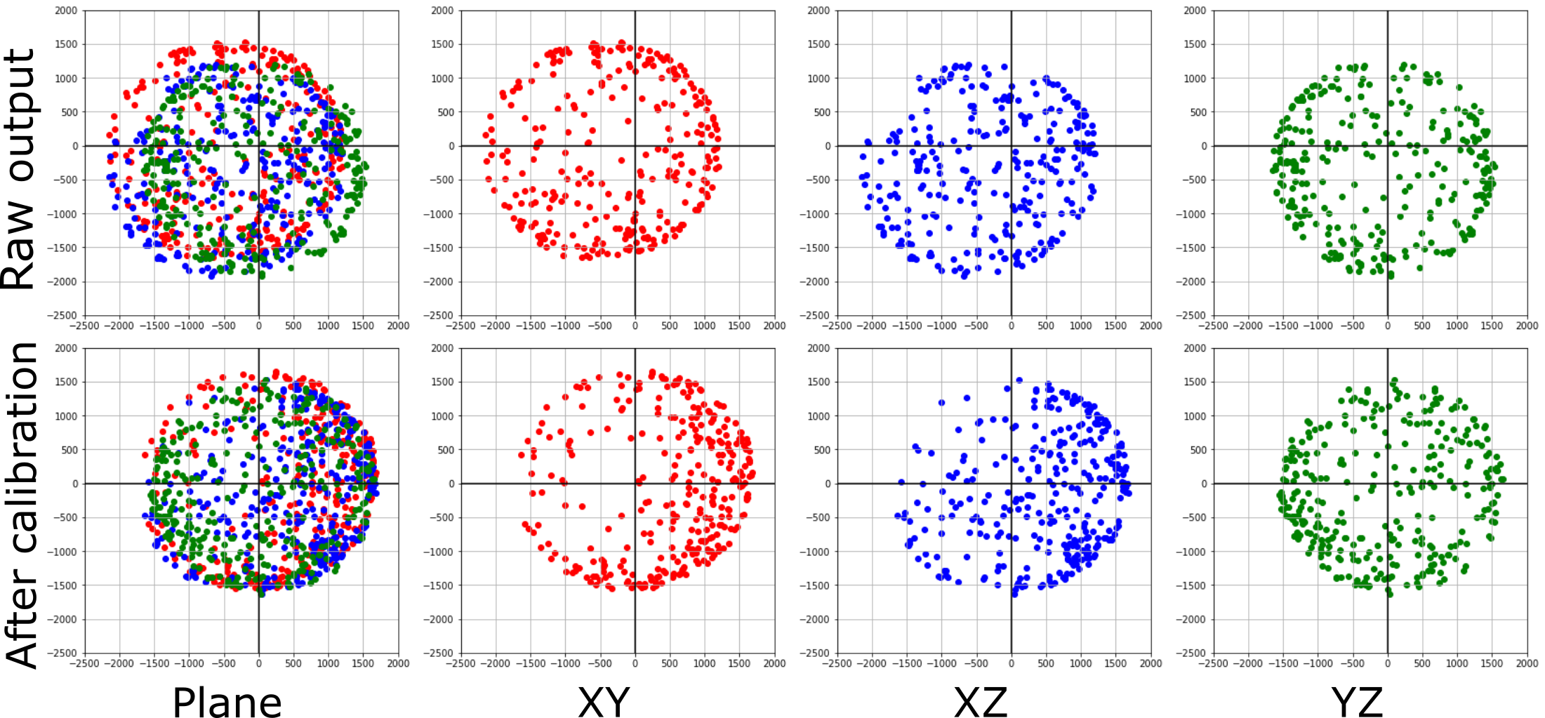
    After sorting this out we started printing data on serial monitor and noticed that something isn’t right. To have a better idea of the output data we decided to plot it into graphs using Python as you can see on the image above.

    Because it is a three axis compass, points are plotted into three planes, in the first column all three planes are shown overlapping and then each plane separately. In the first row are plotted unchanged data from the compass module. As you can clearly see points are forming a circle which center isn't same as zero in the graph. The reason is that values have some offset that makes calculating correct azimuth from these values impossible.

    To get rid of the offset a calibration is needed. It's done by rotating compass ideally in every possible direction and looking for maximum and minimum values for each axis. After calibration is done maximum and minimum values are saved (in present version of software it's not fully functional) and then values read from compass are modified such that there is almost no offset.

    Corrected values are shown in Graph in the second row, as you can see it's much better. Azimuth calculated from these corrected values is quite accurate. Problem is when two axis from whose azimuth is calculated aren't horizontal, if compass module is tilted on side azimuth changes. We plan to address this problem in future by using compass module with accelerometer and then compensate the tilt.


  • Headband Construction

    Tomas Kosicek08/26/2018 at 16:17 0 comments

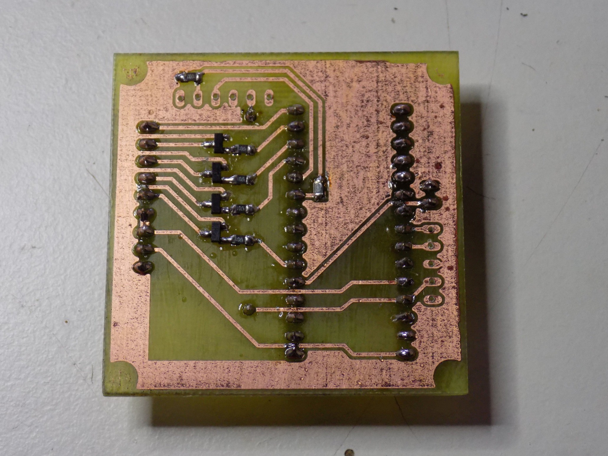
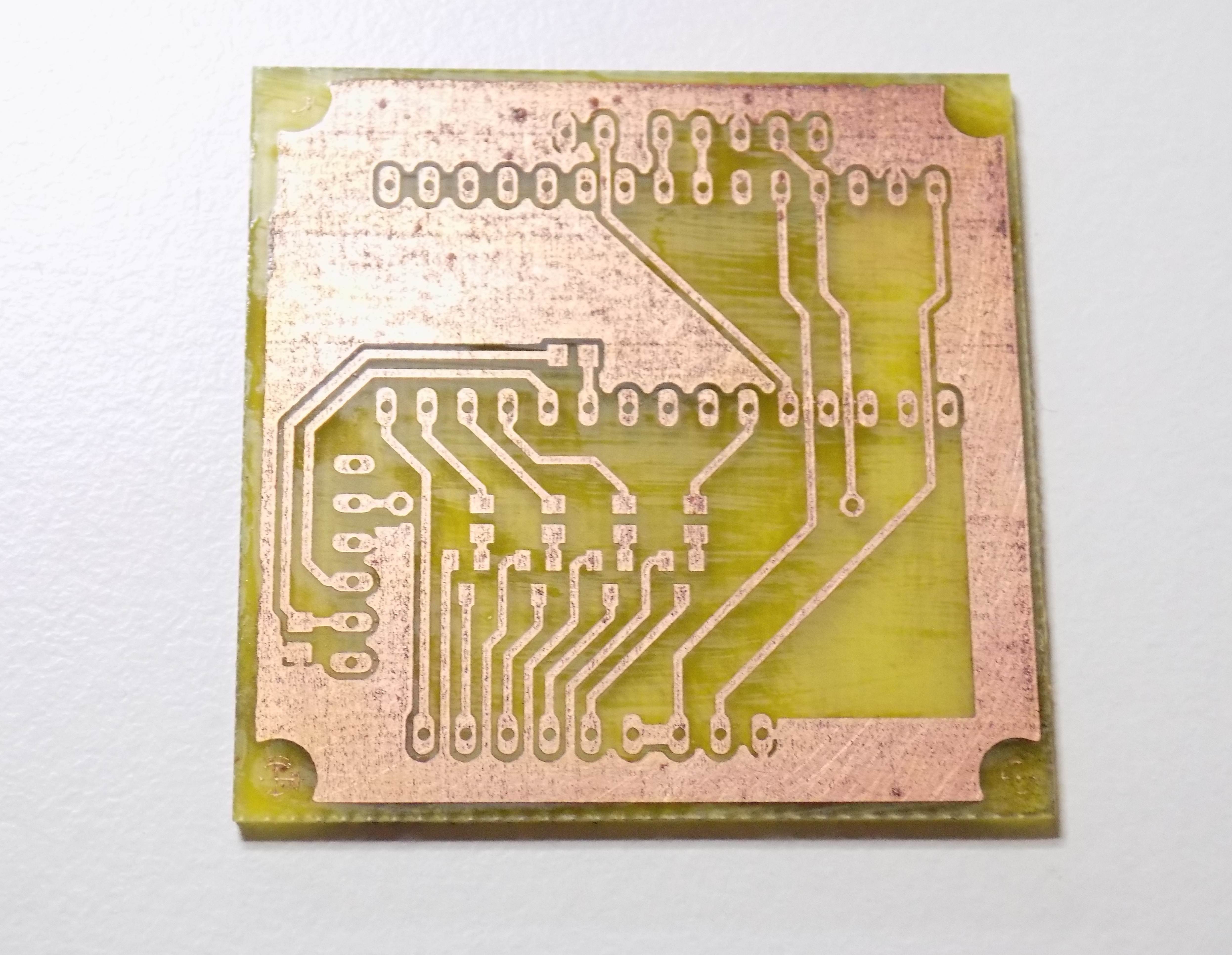
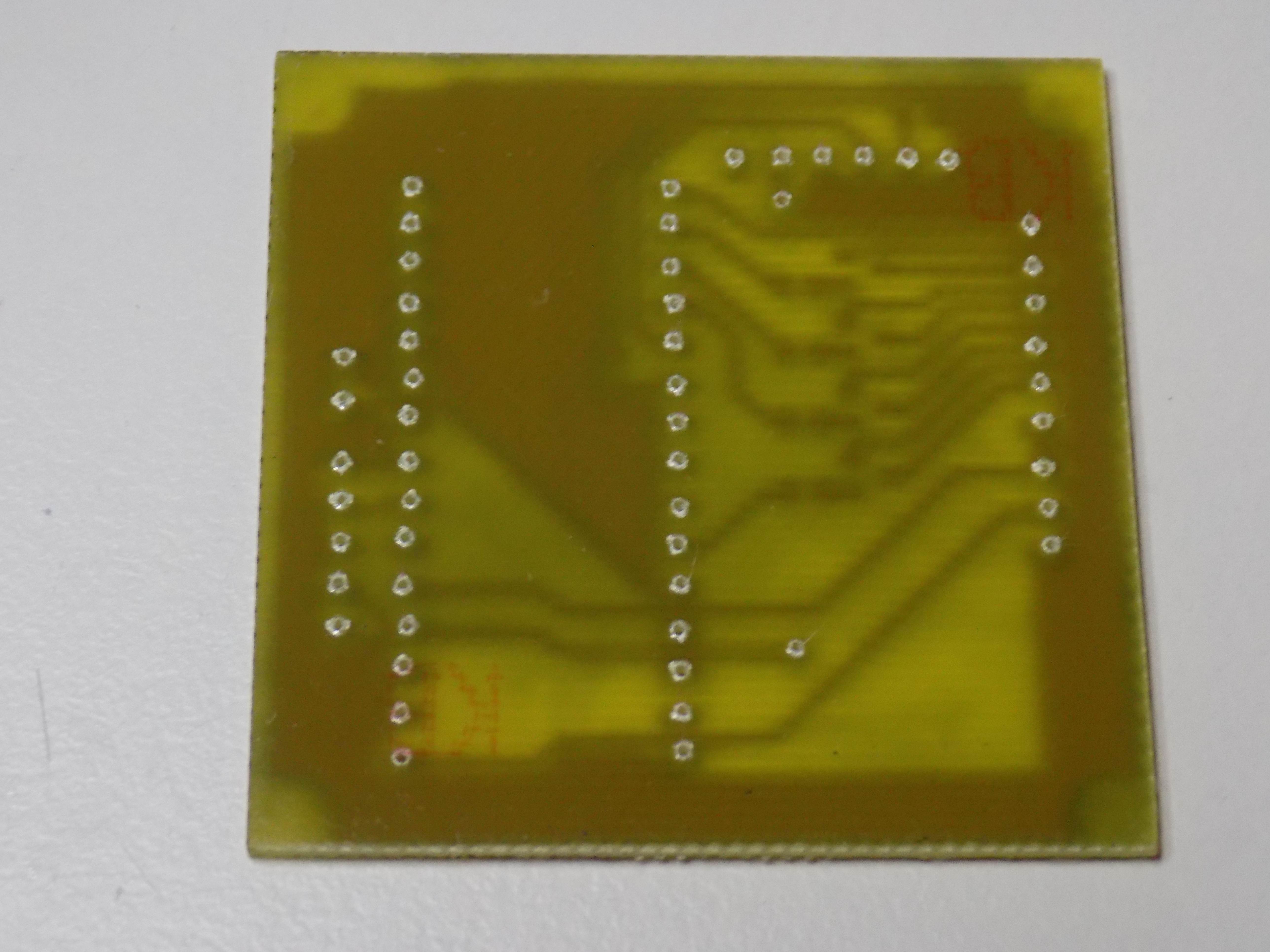
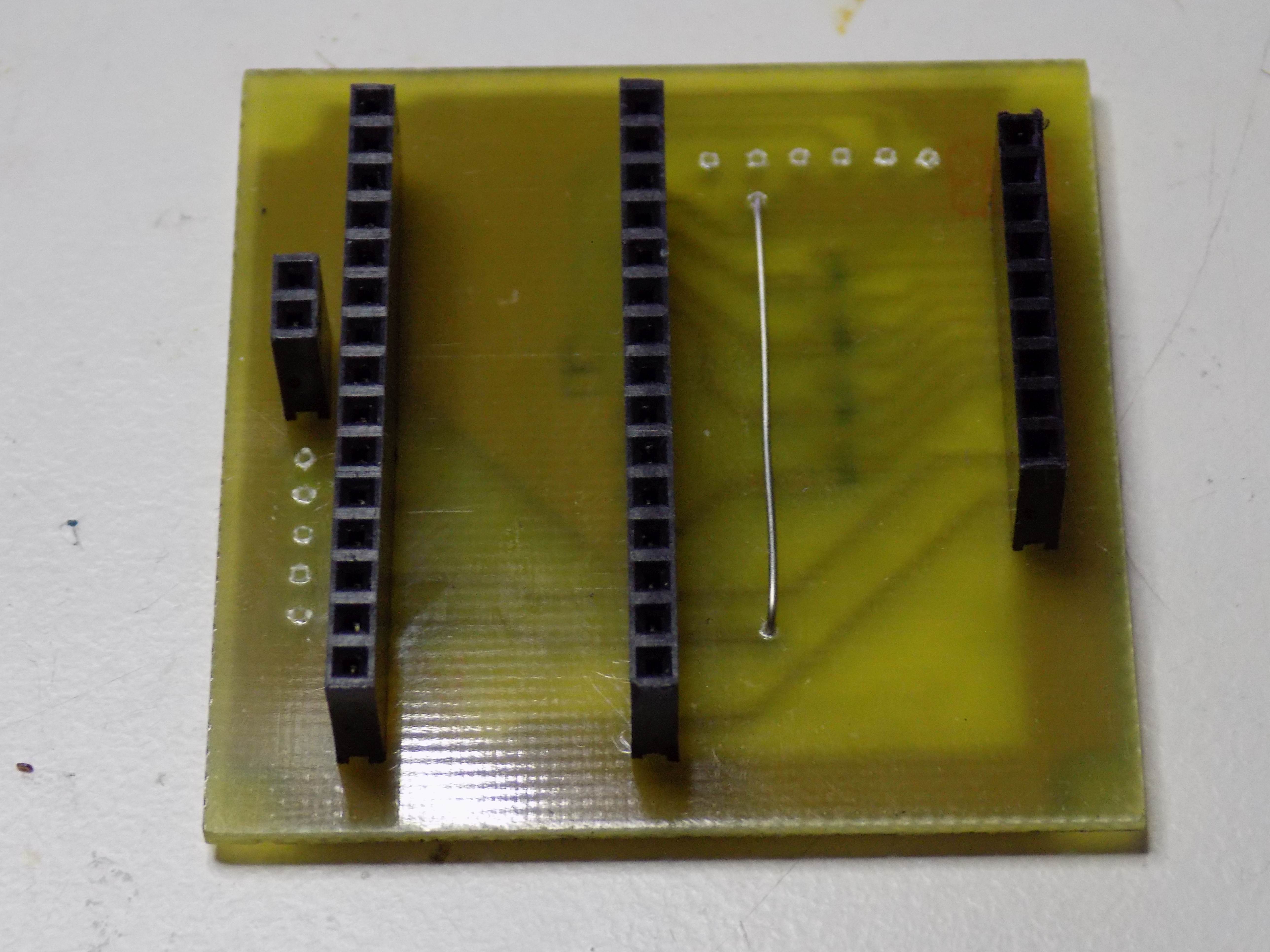
    Once we finished testing our circuit in breadboard it was time to make it more solid. We considered few options how to connect modules and other components together, namely connecting modules with wires and leave them sort of loose in the box but because there are other components than just modules it wasn’t suitable solution. Another option was to solder everything onto a universal PCB, this would be better and quite easy to make but we planned to use SMD components to save some space and also it would be harder for us to document it properly and for other people to rebuild it, therefore we’ve chosen slightly more difficult approach to make custom single sided 50x50mm PCB which you can see in photo below.

    By far easiest and fastest way to make reasonably good quality PCB at home was using toner transfer method. After ironing toner onto copper we etched it in ferric chloride, drilled holes and soldered all the components. Bottom side of the PCB doesn’t look so pretty because some toner left stuck to it. In the project files you can find image of the PCB in 600DPI and placement of components.

    Power management

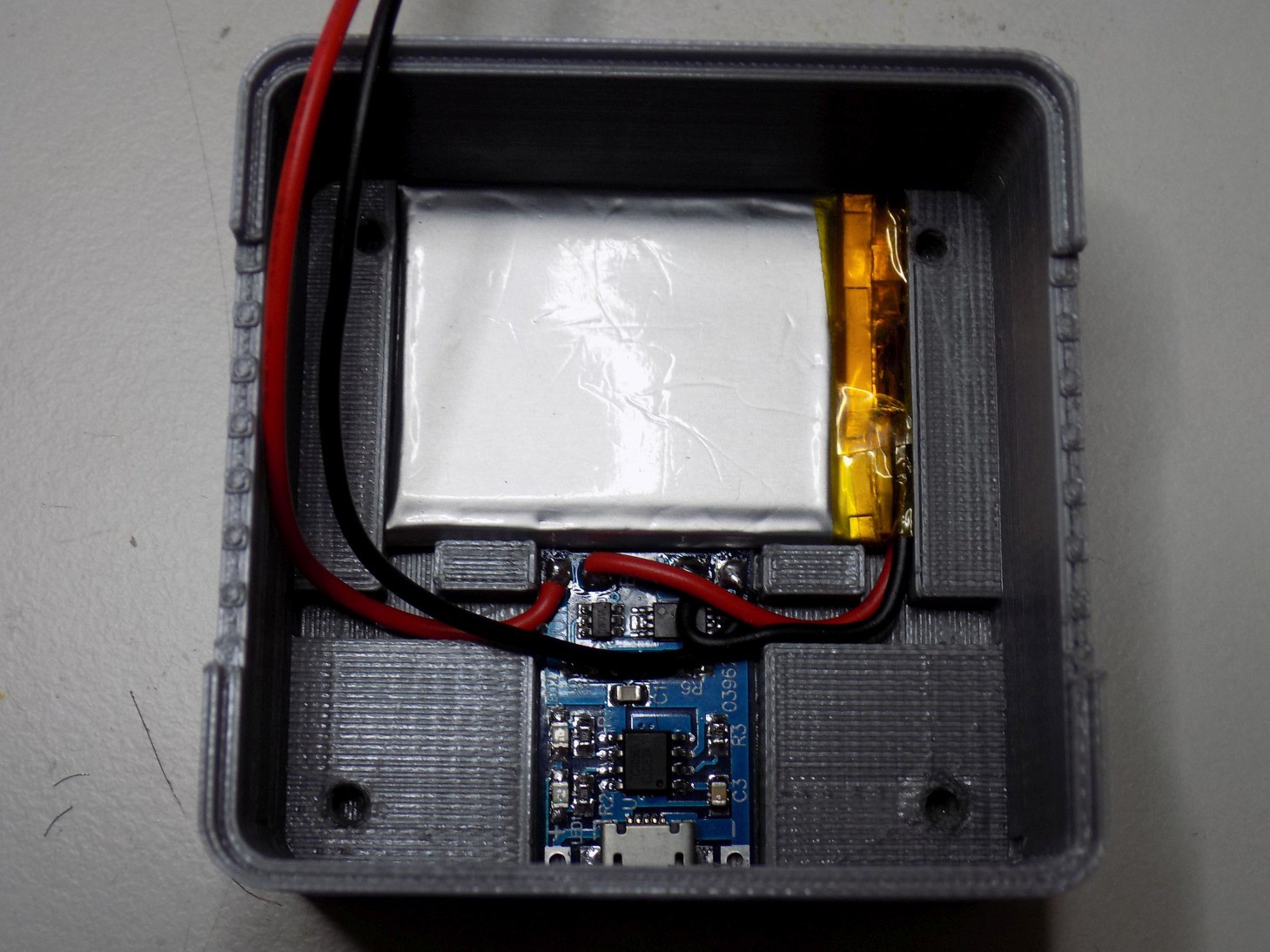
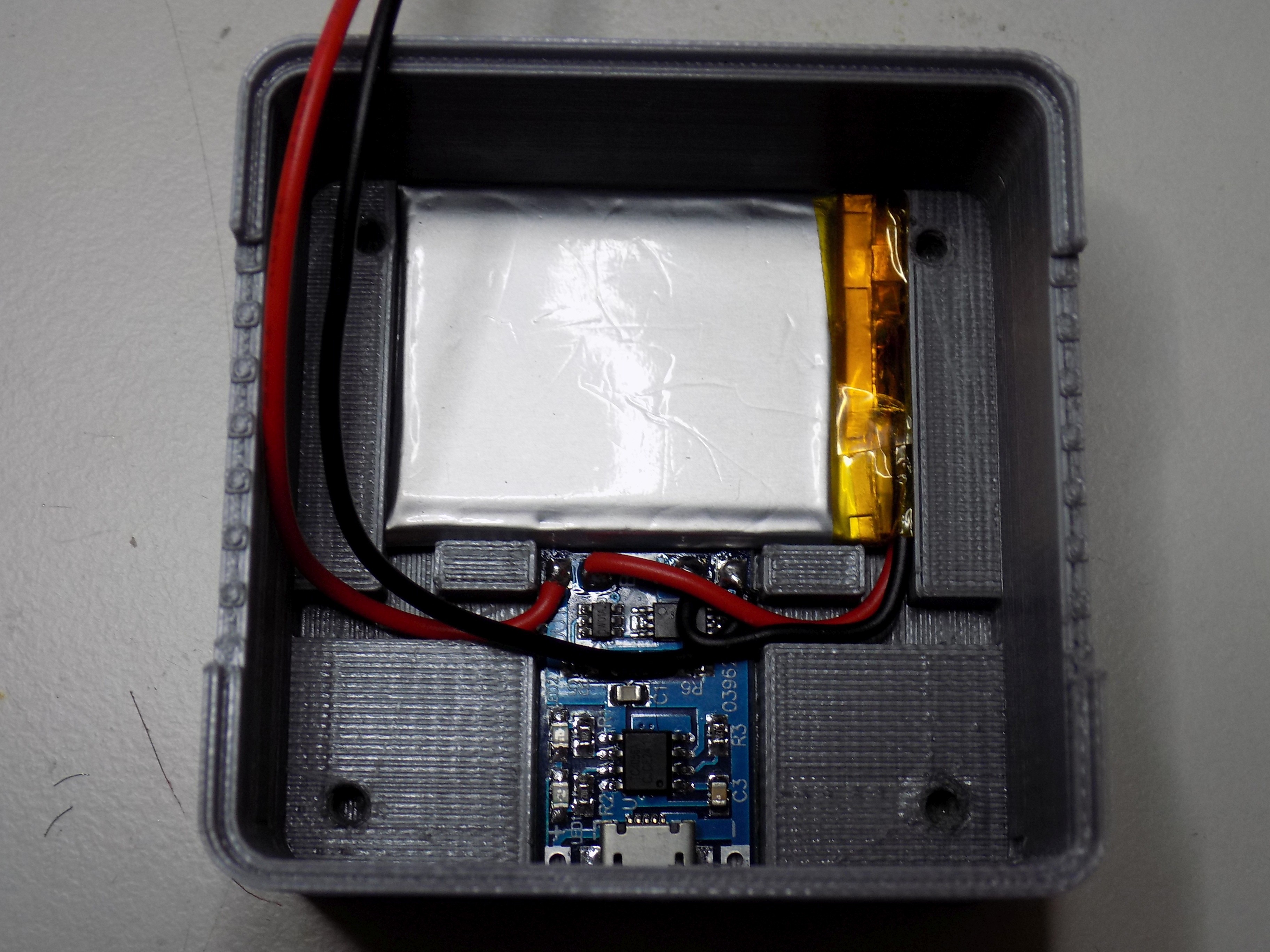
    For Headband to be a wireless device as it is, it needs some way to store energy. For this purpose we’ve picked a LiPo battery with dimensions 4x30x40mm and 550mAh capacity. Together with 03962A charger module it lies on the bottom of the box. Charger module takes care not only of charging the battery but also protects it from overdischarge by disconnecting it from the circuit when battery voltage drops under 2.5V and shortcircuit by sensing overcurrent. There is also a micro USB connector on the board of the charging module which serves as easy way to charge the Headband.

    Initially we planned to have electronics in Headband running on 3.3V but when we got all modules together it got more complicated. Arduino Nano board is supposed to be running on 5V and it has its own 5V voltage regulator, on the other hand both HC-06 and GY-271 modules use 3.3V and they are also equipped with onboard voltage regulators. We faced dilemma of either run everything on 3.3V and hope that arduino will keep working properly or somehow get 5V supply. We’ve chosen to play it safe and use MT3608 step-up boost converter to increase voltage from battery one to approximately 6.5V and then run it through Arduino’s voltage regulator to get stable 5V supply. However in future we want to use only 3.3V, it would be possible to use for example Arduino Pro Mini which is intended for this voltage and LDO voltage regulator connected directly to battery.

    Box

    Box for the electronics has dimensions of 60x60x30mm, it was 3D printed and consists of three parts: bottom, top and spacer, all STL files are uploaded on this project. Basically bottom part contains everything and top serves as lid. Between these two parts are two gabs where rubber comes through into the box. Top part is firmly held in place by four M3x15mm screws, this and small teeth in gabs ensures that rubber won’t fall out. Between battery and the PCB is placed thin 3D printed sheet which acts as spacer and ensures that sharp leads on the bottom side of the PCB would not damage the battery. PCB is fixed into the box with four standoffs in its corners into which comes screws.

    Box with electronics is only one part of the Headband. The other part is rubber band which comes around your head and in which vibration motors are held. Rubber band is 50cm long and 60mm wide, it is folded in half and inside are placed motors and wires connecting them. Each motor is placed inside 3D printed housing together with LED, its resistor and a diode. We bought vibration motors in local store and in future we may switch to flat ones and omit the whole housing. The only purpose of LEDs is to show in photo or video which motor is currently active and in future we will probably get rid of them.

    Vibration motors can’t be driven...

    Read more »

View all 11 project logs

  • 1
    Making the PCB

    First step in making your own Ariadne Headband is to make PCB. You can get it made from professional manufacturer using Gerber files which are attached to our project site or since it is only single-sided board you can quite easily make it at home using toner transfer method as we have and shown in Log number two or any other PCB manufacturing method you are experienced with. All files necessary for making PCB at home are attached to project site. After you have done PCB start populating it firstly with SMD components then continue to the other side of the board and solder one wire jumper. After that solder pin header connectors. In the images below you can see etched, drilled and finally PCB mounted with components.

  • 2
    Printing Parts and Placing Battery

    Next step is to 3D print all the parts for boxing for the electronics. You can find all the necessary STL files attached to this project. After printing box-bottom, box-top and box-spacer take 03962A Lithium battery charger module and superglue it to the bottom of box-bottom part such that micro-USB port will come through the cutout in the wall of the box. Then place lithium battery on the bottom and solder its wires to B+ and B- pads of the charging module as you can see in the image below. Since we have made upgrades to the Headband you have to make cut into the wall of the box for MOLEX connector and glue piece of velcro on box-top part.

  • 3
    Wiring It Together

    Next comes some wiring. Add sliding button into cutout above charging port and solder wire from charger module’s OUT+ pad to two of its terminals. To the last terminal of power switch solder two wires. One of them connect to IN+ terminal of MT3608 step-up converter and the second to pin header male connector as is shown in the schematic. From MT3608’s OUT+ terminal solder wire to pin header right next to the previous one. From OUT- terminal of battery charger module solder one wire to the pin header connected to GND of the PCB, second wire connect to MT3608’s IN- terminal. Solder two wires approximately 7cm long to tact switch and PCB terminals for it. Solder wires from piezo buzzer between arduino's pin number 5 and GND. Also solder 5 wires about 5cm long to MOLEX Mini-Fit 5569 5-pin connector and pin header.

View all 6 instructions

Enjoy this project?

Share

Discussions

Similar Projects

Does this project spark your interest?

Become a member to follow this project and never miss any updates