 Ellie T
The Make book suggested that for 555 oscillating circuits similar to this, the frequency can be calculated with
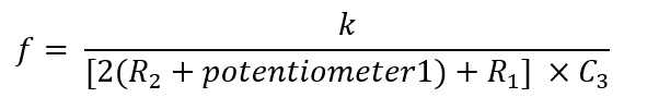
I attempted to achieve greater frequencies by reducing R1 and R2, but the high current caused the resistors and chip to be hot. The constant k depends on the other components in the circuit. If I define k = 1440 as given in the book’s example, my maximum frequency should be around 260 MHz. However, the measured range of oscillator was only 55-194 kHz. This big difference is probably due to the k value due to other component’s differences.
The variable RC filter was controlled by potentiometer2 (P2). The resistance on P2 was varied to suit the frequency and smooth out the square waves.
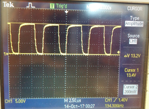
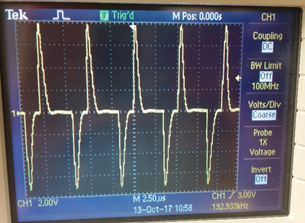
The image on top shows the output without the load, and the image on the bottom shows the output when the load is connected. Varying the frequency (with P2) revealed all sorts of curve shapes across the primary coil, and this ‘spiky’ voltage curve induced the best results on the secondary coil
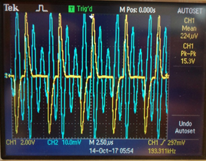
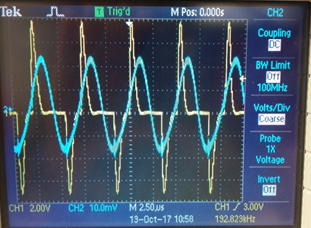 The blue curve on top shows the voltage across the secondary (receiver) coil with lots of higher frequency oscillations. The blue curve on the bottom shows a nice sine wave with the higher frequencies filtered out. Based on the RC equation below a 1pF capacitor was needed for a frequency of around 192 kHz.
f = 1/(2*pi*R*C)
When the frequency is greatly varied, however, another capacitor will need to be used to filter out the ‘extra’ higher frequency waves. So that's a problem with varying frequencies hmmm.
Discussions
Become a Hackaday.io Member
Create an account to leave a comment. Already have an account? Log In.
Ah I must've been forcing the little fella to push limits hard! Thanks for pointing that out.
Are you sure? yes | no
Might want to _READ_ the datasheet to see what frequency your 555 is capable of first. See "
Parametrics - Frequency (Max) (MHz) " Just because they give you an equation doesn't mean that there aren't limits due to the components.
http://www.ti.com/product/TLC555
Yes, there are faster versions of 555.
Are you sure? yes | no