Sensor with driver-board and arduino
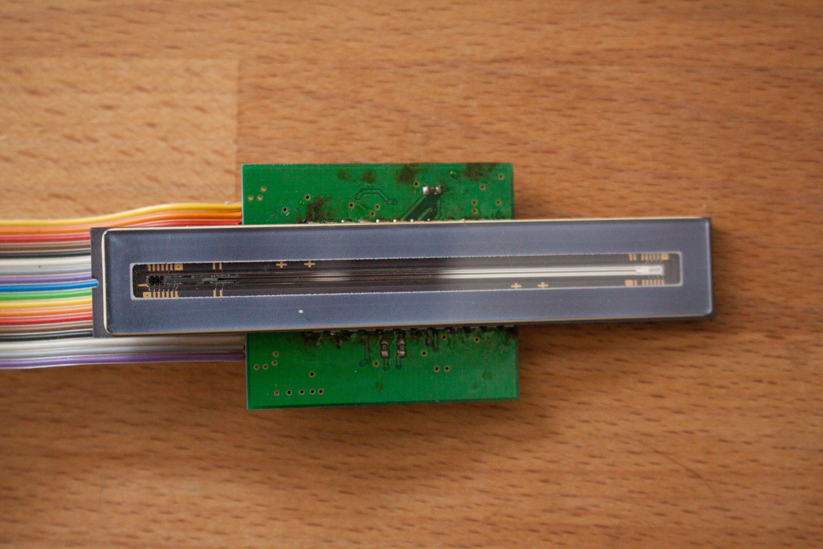
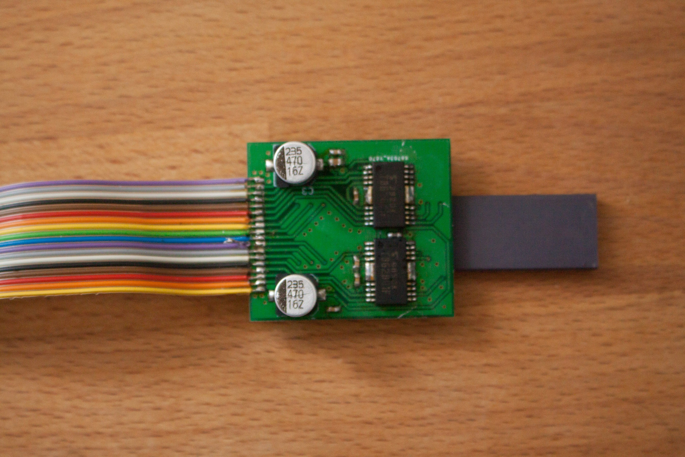
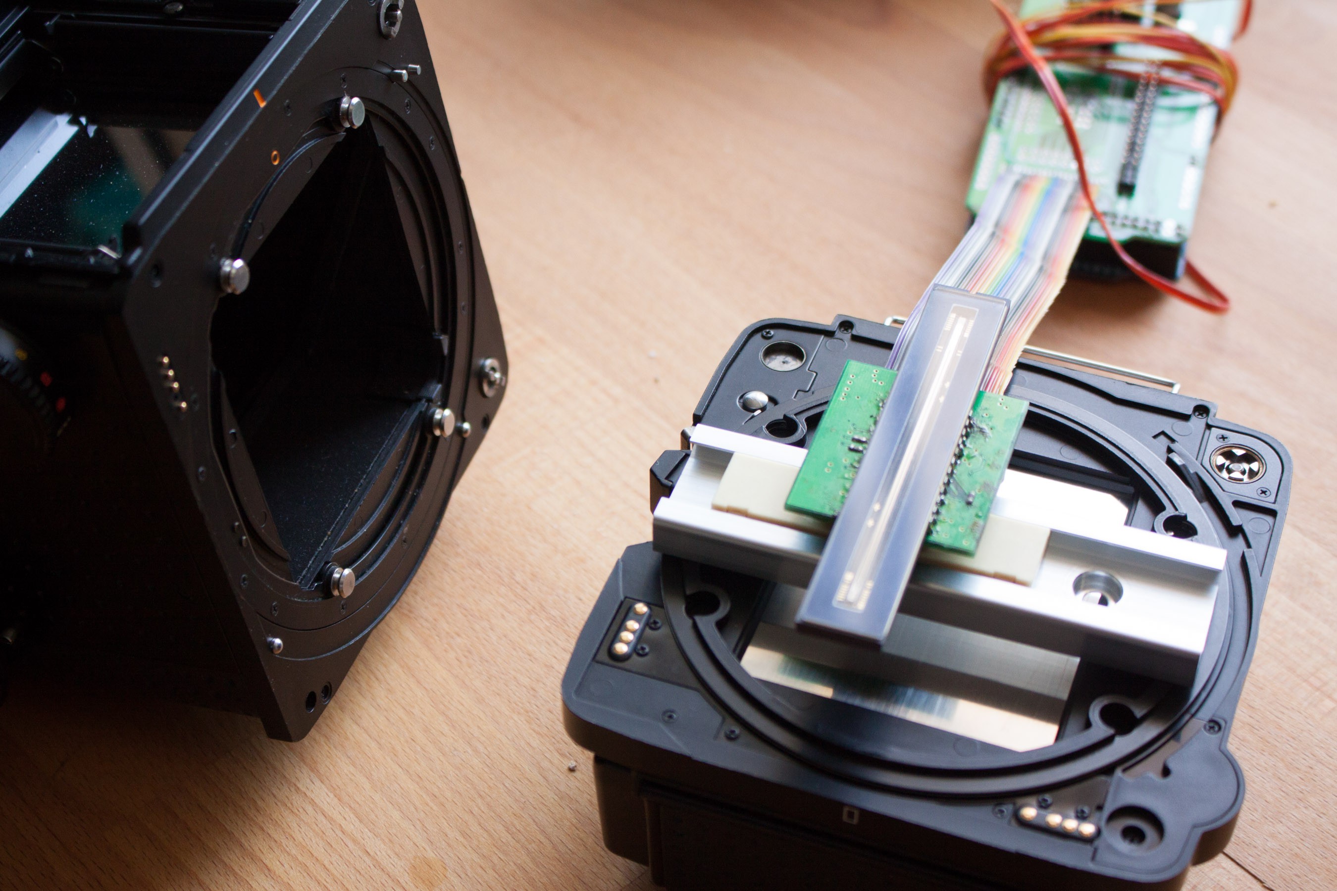
This is the toshiba tcd2700c linear ccd. I made a board with the drivers. Interfacing the sensor with the arduino was rather tricky, as it requires a differential clock and draws quite some current. The first versions didn't use the original toshiba drivers and simply didn't work.
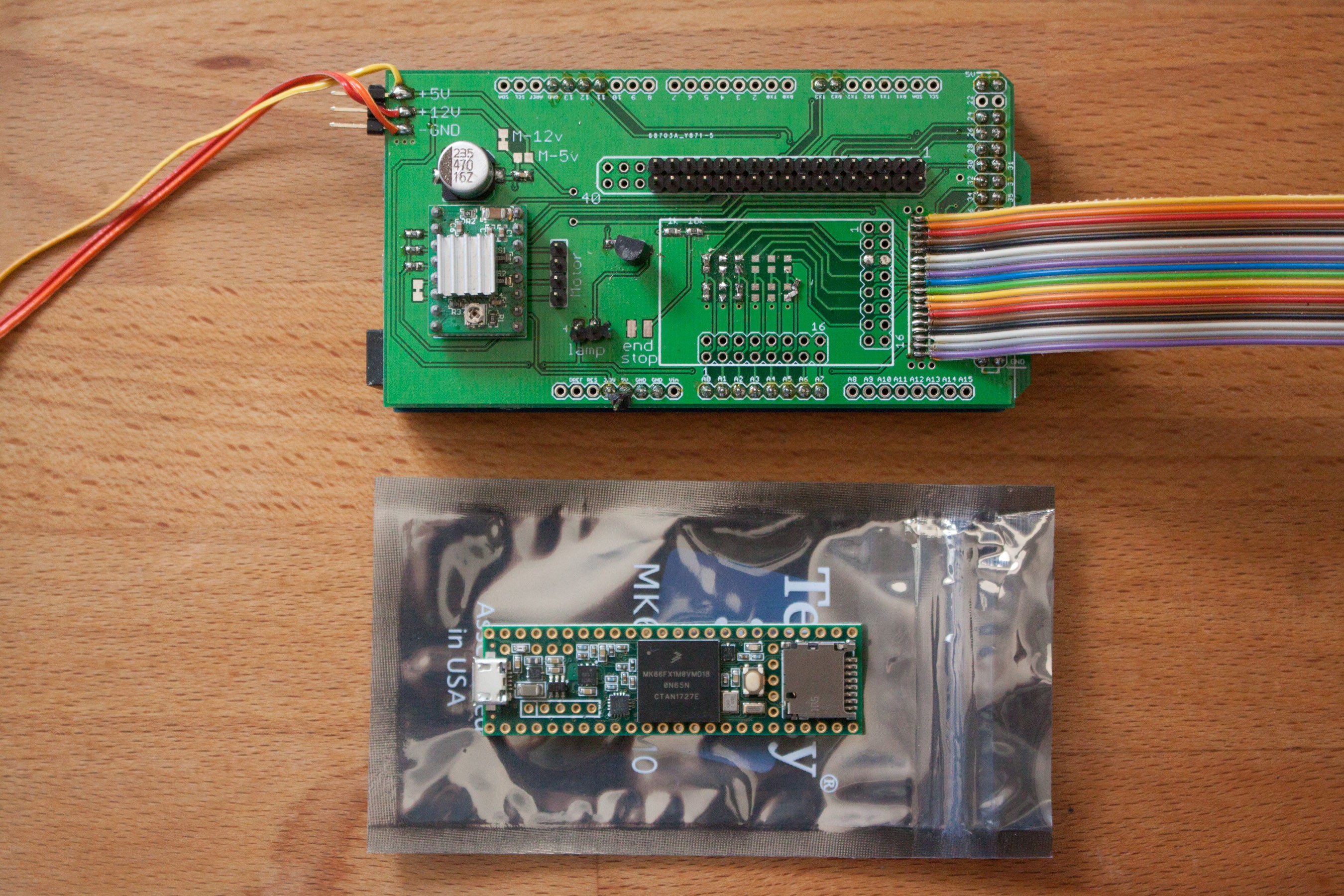
The PCB on the arduino already has a stepper driver on it, because I wanted to use it for a non-portable scanner, so the arduinos size was no problem. In this project I want to replace it with a Teensie 3.6.
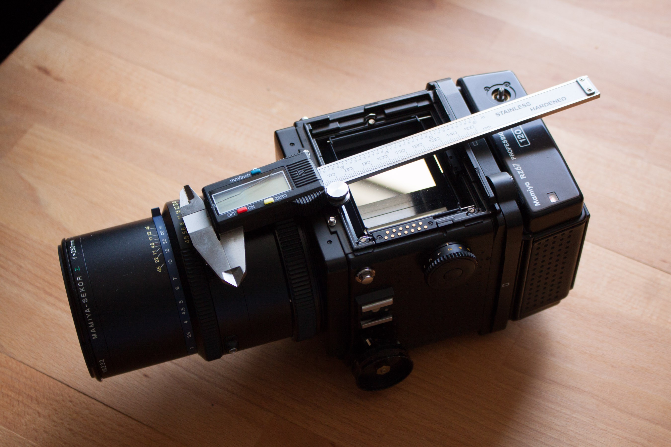
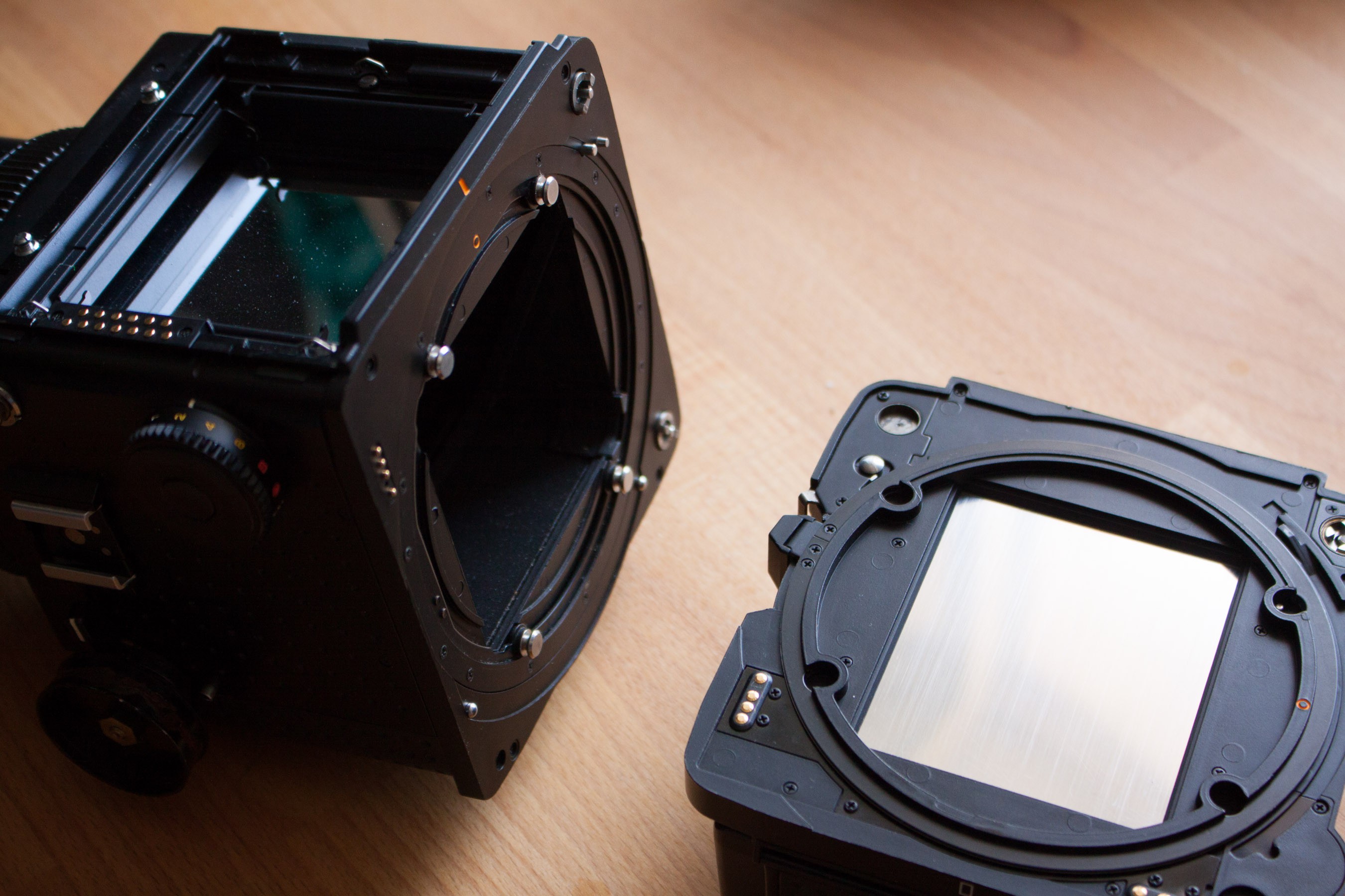
Mamiya RZ67 camera + lens + film back
Comared to any digital camera, even large DSLRs, this thing is huge. The viewfinder is 7x7cm large. A very unique and nice feature of this Camera is the rotating back. So a film back with 6x7cm area can be rotated to be used for portraits or landscape.
Linear guide rail
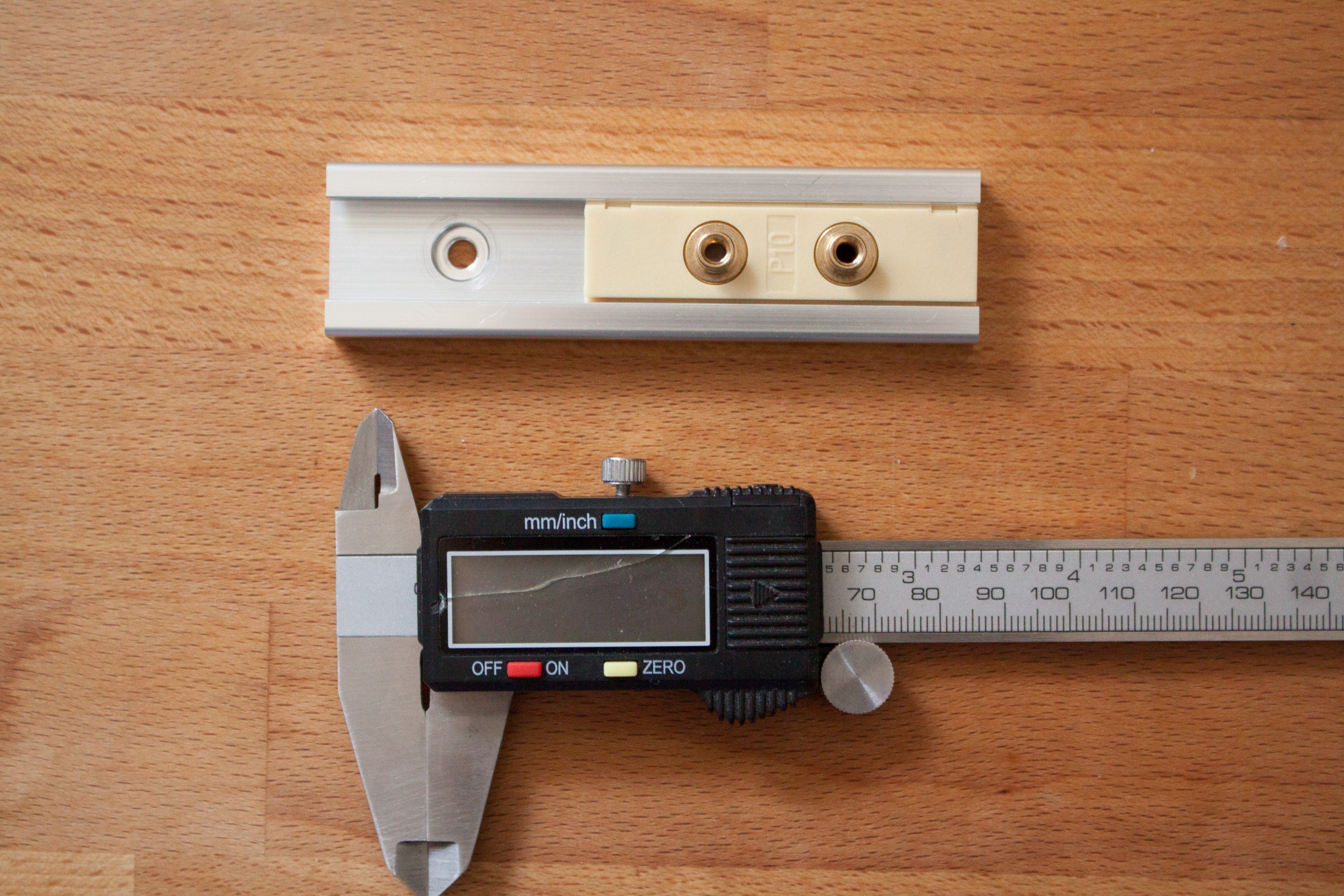
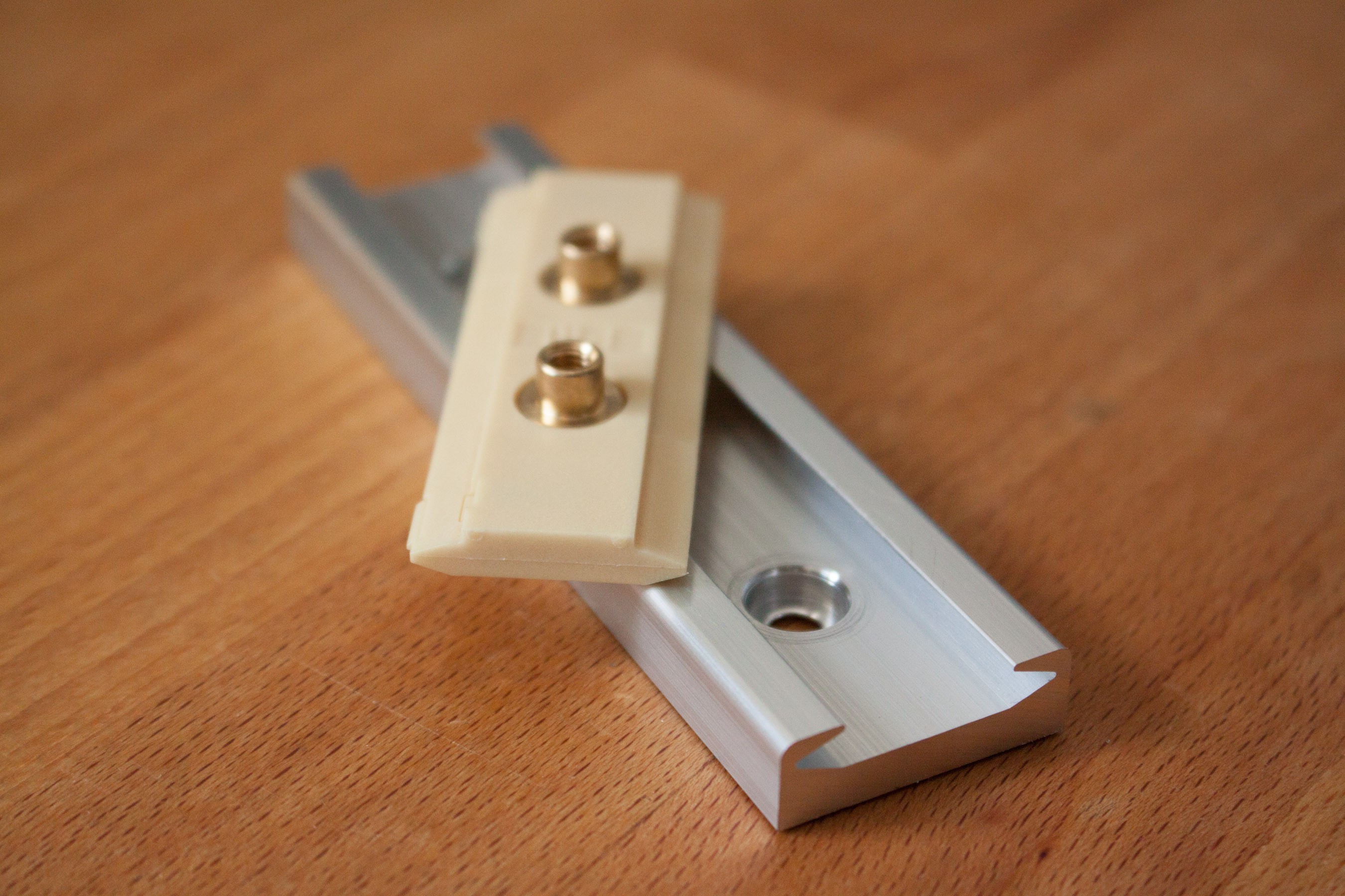
The used linear guide rail is a drylin N prism rail with 27mm width. The carriage has a 10N preload and runs very smooth. In the second image you can see the spring loaded part at the bottom left corner of the carriage. It pushes the carriage up and sideways, so when only a minimal mechanical force is applied it should be very precise movement.
Precise positioning of the sensor is very important, since the pixel-width and thus line width is only 8μm.
Discussions
Become a Hackaday.io Member
Create an account to leave a comment. Already have an account? Log In.