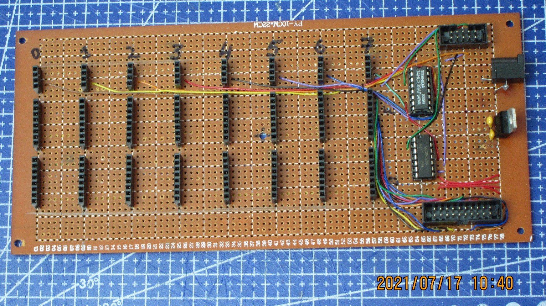
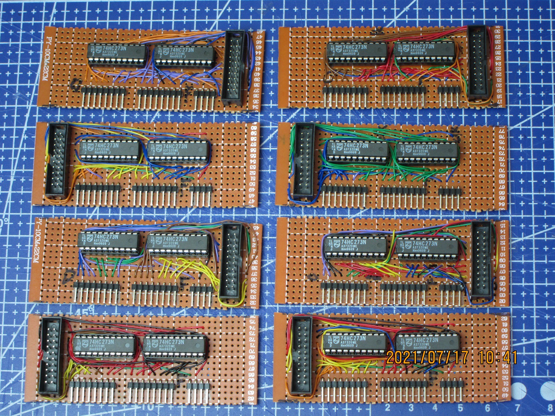
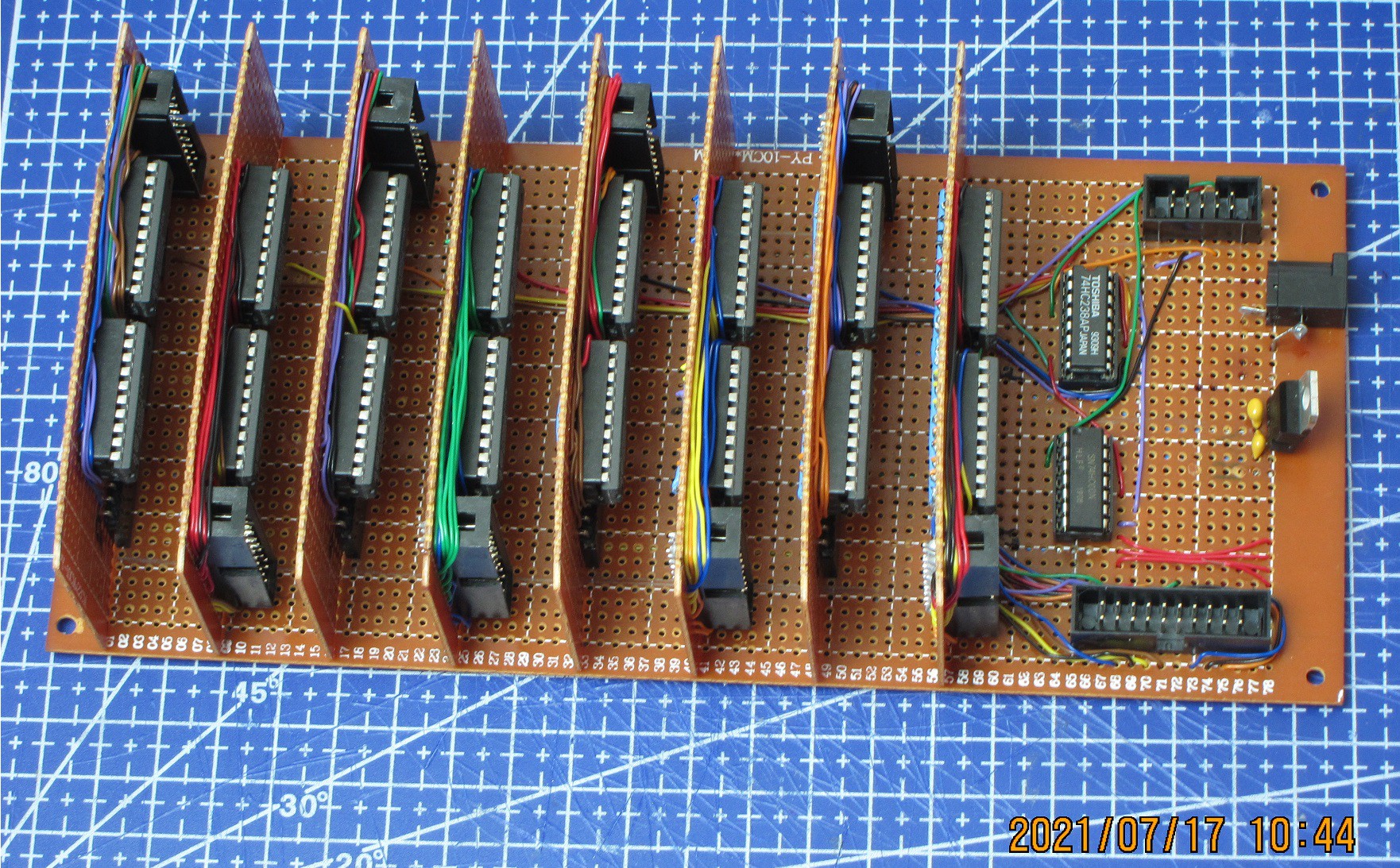
The "Backplane" board along with 8 register mini-boards are completed.
This is the main part of Register File, where data is being held.
Each mini-board contains a 16-bit register and output IDC connector, as well as a row of pin header connectors through which they connect with backplane board. The backplane itself provides data input, and selection of register to be written, as well as power.
Next part will be LED display of data in registers. It will consist of two boards - one with all the wires and connectors and ICs, and the other will have only LEDs soldered to it, the display itself.
This display really is not necessary for the function of register file, thus it might be thought of as already having all the needed parts for the operation. But the display of register contents is what I want, and so it will be done. It will have great value as diagnostic tool as well as just a bunch of pretty lights. Aside from displaying contents of registers, it also will have indication of which register is written to, which are used as Src1 and Src2 for ALU, and which have its data output directly to bus.
1. The backplane board:

2. Register mini-boards:

3. All boards assembled:

 Pavel
Pavel
Discussions
Become a Hackaday.io Member
Create an account to leave a comment. Already have an account? Log In.