 Pavel
PavelIn previous post I wrote about planning to add a funnel shifter (an extended barrel shifter) to this CPU design. Now, I have designed a 4-bit prototype, and implemented it in FPGA, it has all the needed control signals, and performs all operations I intended it to perform. The 16-bit version would have more bits controlling shift amount, but other control signals will stay the same.
What is the Funnel Shifter?
This is an extension of the Barrel Shifter, in a sense that it is 2 times wider than machine word (barrel shifter usually is the same width as word), and can manipulate data on 2 consecutive registers as if was one double-sized register, and extract the arbitrary word-sized bit field. Thus, it takes two words as input, and outputs a single word. In my implementation, there are some additional functions, and caveats.
Here is the schematic I drawn (it is final, 7th version), which helped me in writing Verilog description:
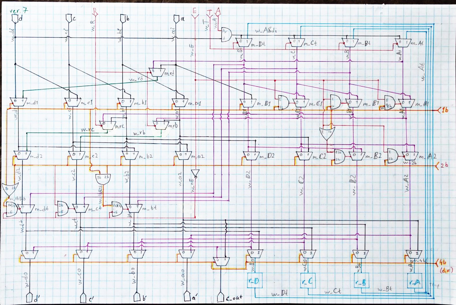 On the schematic, there is the funnel shifter itself, comprised of a bunch of 2:1 muxes with a little sprinkling of AND and OR gates, as well as temporary register represented as 4 data flip flops r_A through r_D (blue squares). This register holds shifted-out bits that could be retrieved later, with special MOV operation, or used in consecutive operation to facilitate multi-word shifts/rotates.
There are 5 types of shifting operations this circuit is capable of:
1) regular shifts to the left or right;
2) arithmetic shift right;
3) rotate word right;
4) rotate through N bits of temp register*;
5) rotate double word.
*This is expansion of Rotate Through Carry, but can use several bits from temp register.
There are 4 control lines defining general operation (red, with inputs on top):
A: Arithmetic shift;
R: Rotate (for single-word rotation);
T: Use the Temporary register;
E: Extended rotation (rotate double-word, has effect only with T).
There are also 3 control lines (golden-red, with inputs on the right) defining shift amount and direction (1b, 2b and 4b).
The temporary register is supposed to be updated only for operations that have T signal high.
As there are 4 control lines, there is 16 possible combinations, but not all of them are useful, and some of them are functionally duplicates. Out of them, 5 combinations are selected to provide 5 operations listed above. Of these, arithmetic shift and single word rotations need to be only to the right.
Rationale for using special temporary register instead of second general purpose register:
there is just not enough bits in instruction for encoding second source register address. I need to provide the source, the destination, and shift amount (or third register containing shift amount), and this is already 9 or 10 bits out of 16-bit instruction, 6 bits that are left are opcode. There is no way to have another 3 bits for yet another source register address.
With global structure of this shifter proven on 4-bit model, the next now is to scale it to 16 bits.
Discussions
Become a Hackaday.io Member
Create an account to leave a comment. Already have an account? Log In.