 Pavel
PavelI had scaled up the model shifter described in previous log to the full 16 bit width. Along the way I found some inefficiencies in design, and corrected for them -- this made circuit to behave slightly differently in marginal ways, but overall change is positive due to some irregularities weeded out. This is mostly theoretical for now, as the circuit exists mostly as various diagrams I drawn while designing it; also I created the Verilog description, flashed it onto FPGA and tested -- it turned out to work correctly.
Here is functional diagram of this circuit:
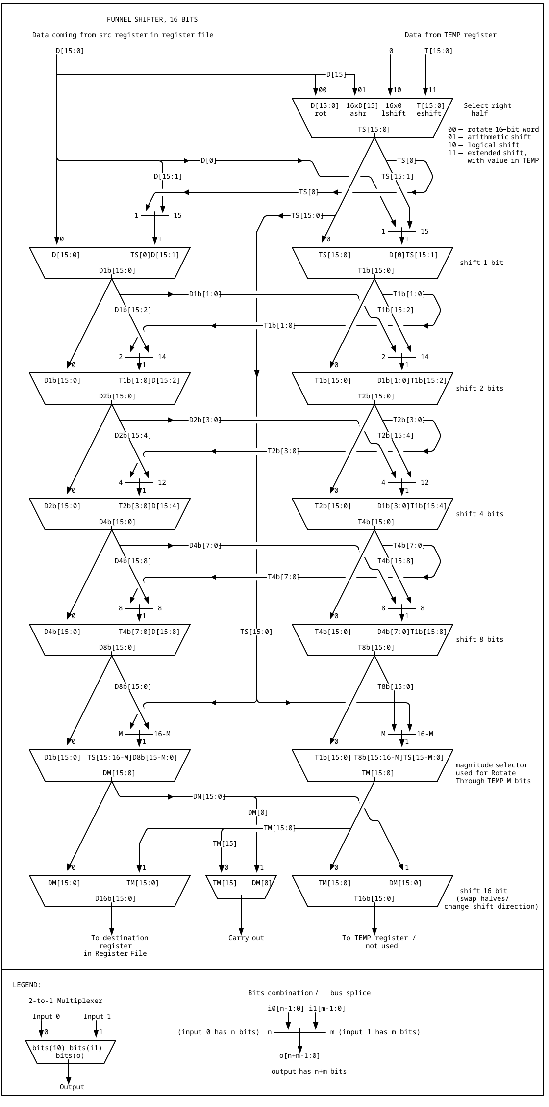
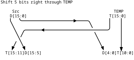
As was written in previous log, this shifter makes use of additional register as source of data, the register is called TEMP, and it is outside of main Register File. This additional register is used only in subset of operations this shifter is capable of, namely, the Rotate Through Temp op (which is like Rotate Through Carry, but extended to several bits at once), and Frame Shift, where a contigous 16-bit field is extracted from combined Src and TEMP registers.
The Rotate Through Temp requires special circuit I called Magnitude Selector. It consists of 2 parts -- the circuit that takes in 4 lines defining rotation amount (1b, 2b, 4b and 8b) and outputs 16-bit value containing from 0 to 15 ones, like this:
0:   0000 0000 0000 0000
1:   1000 0000 0000 0000
2:   1100 0000 0000 0000
...
7:   1111 1110 0000 0000
...
15:  1111 1111 1111 1110
through 16 lines; these lines, each ANDed with enable signal drive the muxes between 8b and 16b selectors. This makes it possible to swap a selected number of bits between TEMP register and shifted bits from Src register; the leftower bits of TEMP stay unaffected:
This one is the more complex part of this whole circuit.
I am thinking of adapting this design to using 74HC family logic, and juggling between wiring complexity and propagation delays, I think at least the last 3 stages should be condensed into one consisting of 8-to-1 muxes (74HC151). This seems more appropriate, as each bit should be switched separately for magnitude selection, and the 2-to-1 muxes (74HC157) are packaged in a way that switches 4 muxes by single select signal.
------------------
Although almost all diagrams I hand drawn, I found a cool website (with editor called svgbob) which turns ascii diagrams into svg images, facilitating line drawings. So the diagrams above were done using it.
Discussions
Become a Hackaday.io Member
Create an account to leave a comment. Already have an account? Log In.