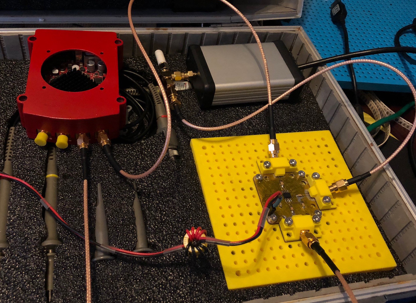
I made the PCB for an SA612 mixer module and assembled the first test build. The only thing missing is the LD1117 regulator so I am just powering it from an external regulated supply.
All seems to be working well, although only tested up to 50Mhz until I build the Si5351 module.
Tons of extra harmonics but thats to be expected with no filtering. Still there was no visible distortion even up to 40Mhz IF with a 10Mhz input signal. Initially I tested with the Redpitaya's function generators and its input in the oscilloscope mode. Unfortunately the spectrum analyser mode doesn't let you turn the outputs on at the same time so I swapped over to an RTL-SDR module to look at the spectrum.

Now to try my hand at UV photoresist PCBs and try get a working VCO with the Si5351
 Colin Alston
Discussions
Become a Hackaday.io Member
Create an account to leave a comment. Already have an account? Log In.