Jarrett
-
Schematics
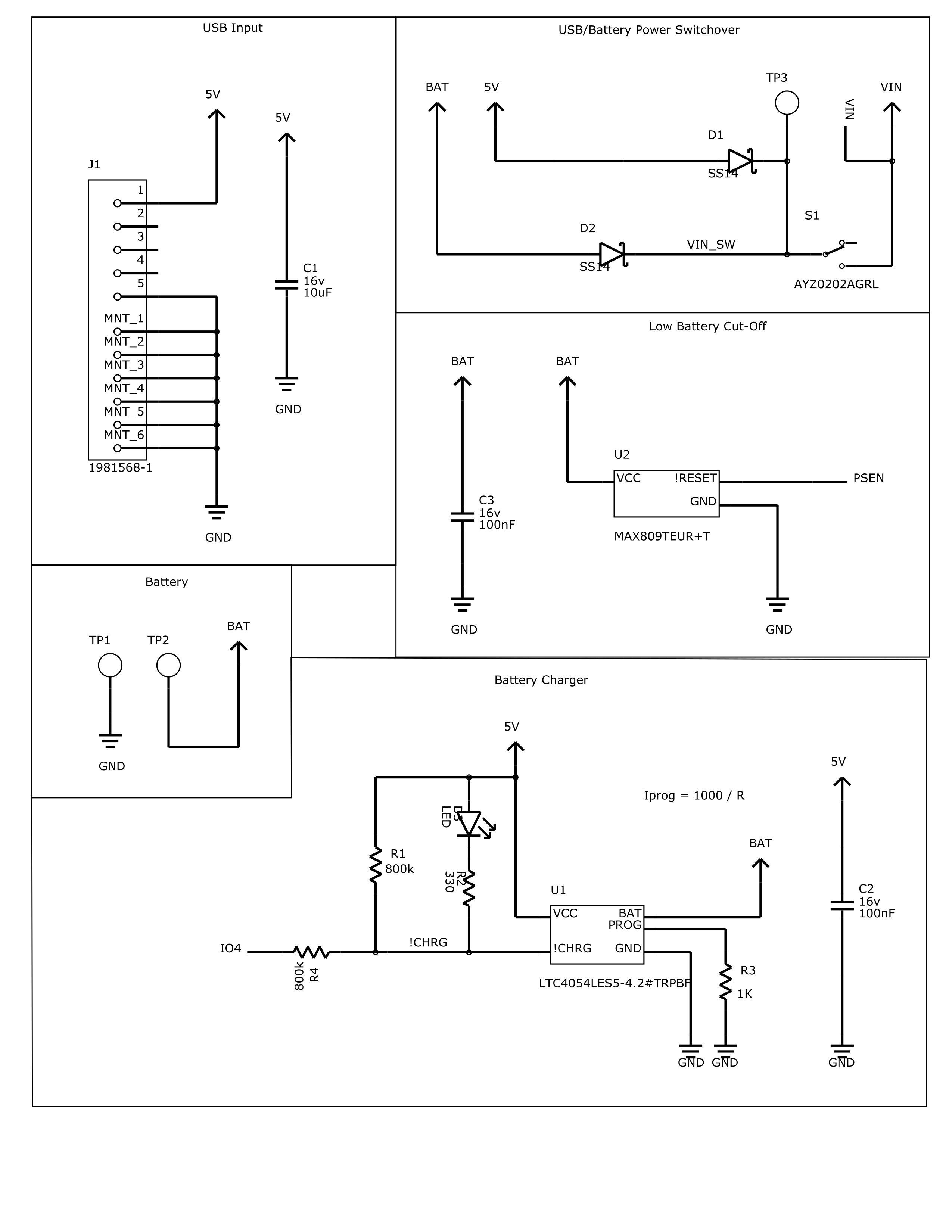
08/22/2018 at 03:44 • 9 commentsLiPo management circuitry is fairly complex, and I couldn't really find any one-chip solutions that weren't $15 for an IC. So I did it properly.
MicroUSB connector, with diodes to select for the higher of two voltages (3v-4.2v battery or 5V USB), to a power switch.
The MAX809 is a low voltage cutoff chip, so that when the LiPo sags below 3.0V, it'll disable to the power regulator and not damage your battery.
The LTC4054 is a LiPo battery constant current charger, to properly charge your battery when USB is plugged in. R3 can be changed to adjust the charge speed. Few of these values are set on the schematic, so don't use 1k, that would be very slow!
The charge indicator LED works according to how the datasheet specs, but there's also some clever connections to allow the ESP32 to be able to read charge status, if desired.
![]()
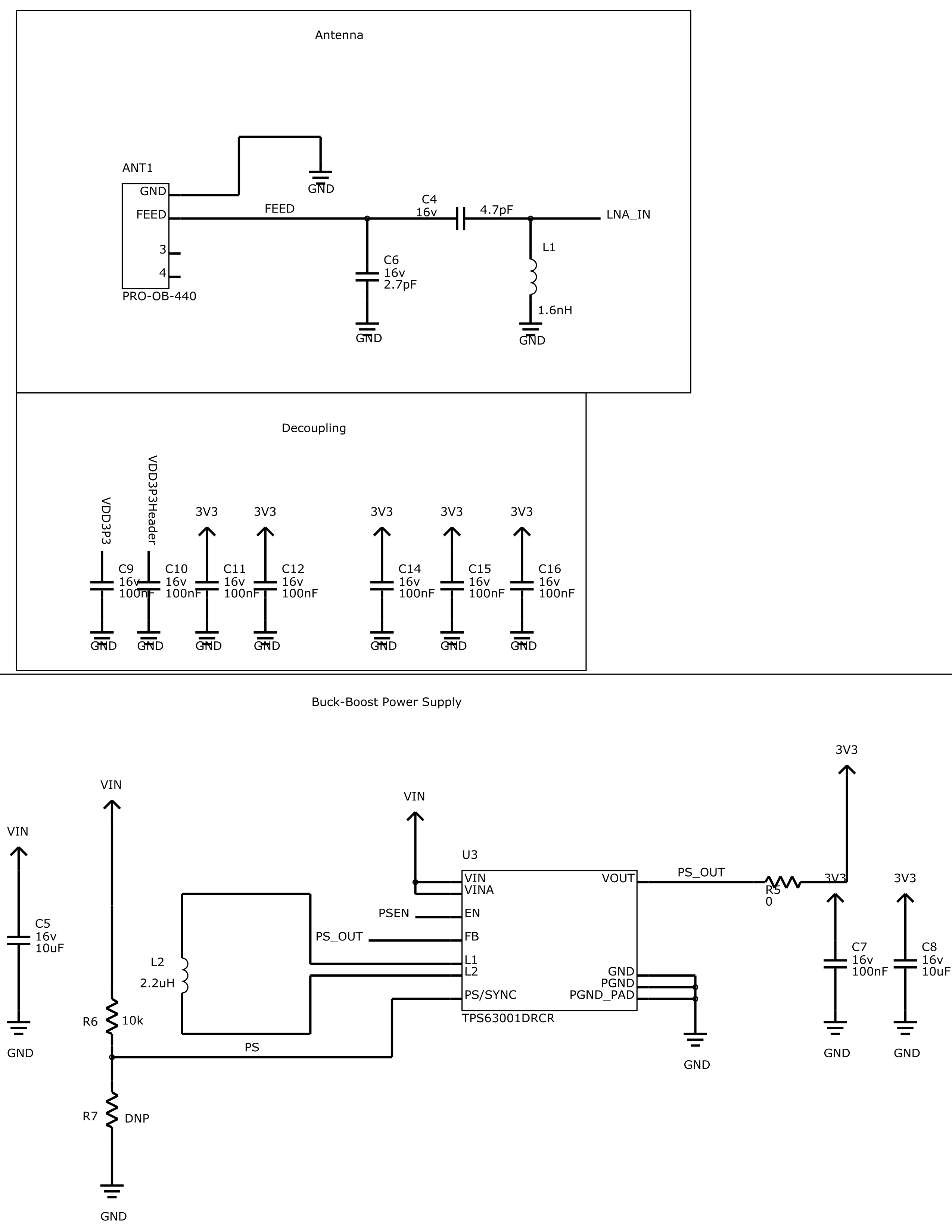
The antenna is a Proant 440 3D antenna for 2.4GHz. These values are certainly subject to tuning when the board arrives, and the inductor might not even end up being an inductor.
The ESP32 I used, a bare ESP-PICO-D4 has a whole bunch of power rails, so requires a bunch of decoupling caps, the usual. I probably won't bother populating a bunch unless they are required.
The TPS63001 is a buck-boost switch-mode power supply, outputting 3.3v and with an input that nicely brackets the 3.0v-5.0v range I'm targeting. Input voltage to this will probably be more like minimum 2.0v-2.6v due to my input diodes, but I might switch those to something fancier.
The output also has a 0-ohm resistor that I could sub out for an inductive choke if I need some better filtering.
![]()
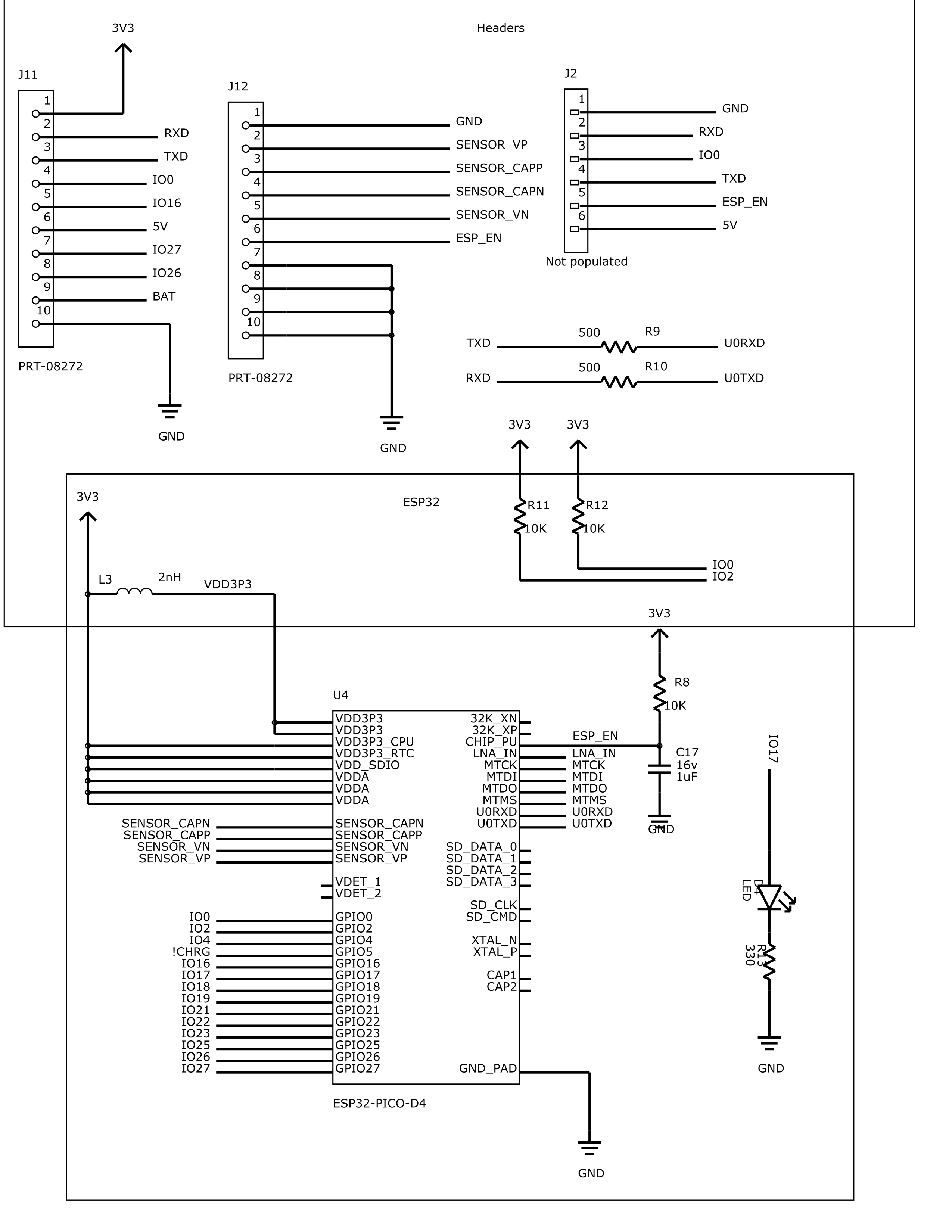
A bunch of headers. J11 and J12 are the castellated edges. Pins 7-10 on J12 are a liiiittle bit janky, because they intersect with my USB port's ground pads. They should make it hard to pull the connector off, though!
J2 I ended up leaving off the PCB, but it has all of the signals needed for programming. They were duplicated to some of the castellations, so no big deal.
And finally, the ESP-PICO-D4! Fairly self-explanatory. I was slightly choked I didn't have room for the JTAG headers.
![]()
-
Lineage
08/20/2018 at 20:00 • 2 commentsDespite baaaarely working at all in the Espressif line of chips, I've done a lot of things on the hardware side, because I like the idea of having wifi in everything. Most of it has been a steady progression forward, to more and more interesting PCB design problems.
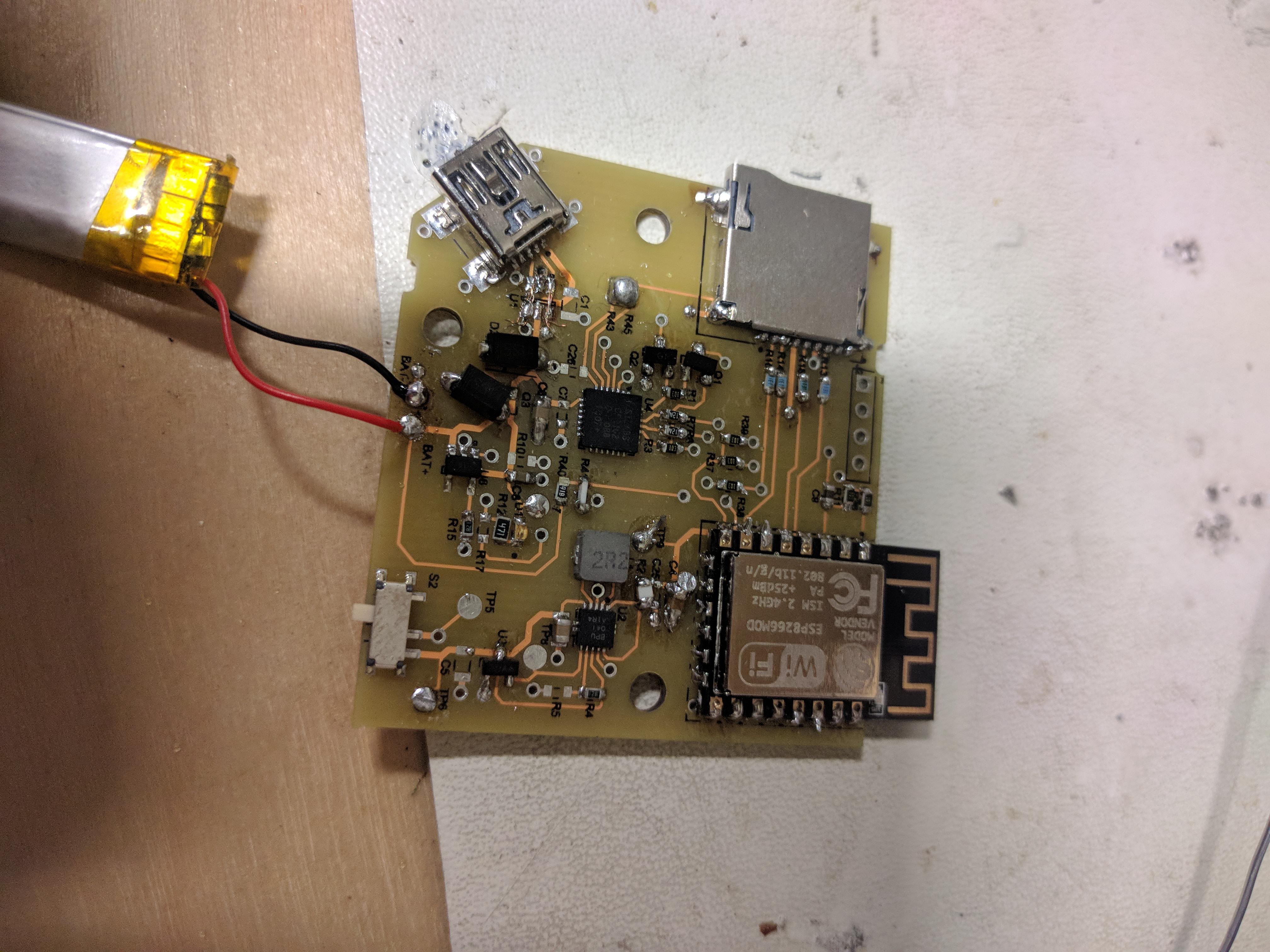
The first dev board I made for them is a LiPo charger for an ESP8266 module, dubbed Sugar Glider (for obvious reasons.
![]()
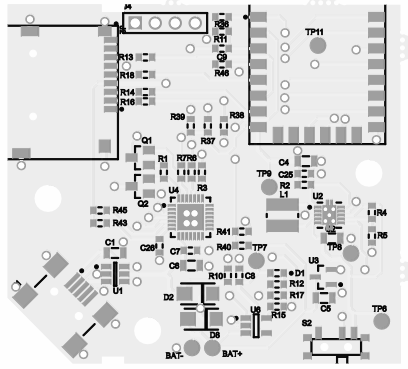
The circuit part of this was pretty hastily thrown together, and didn't really have all the features or cost optimisations I would have liked. So, eventually, I did a test board for rev 2. There isn't a proper write-up for this yet, because it's totally not done.
![]()
As you can see from the soldering job that looks like it was done with a Bic lighter, it had some issues and needed some rework and design fixes. That is totally to be expected, that's why it's a test!
Test 2 with all the fixes is still on the slow boat:
Should arrive by the end of August, and hopefully I'll be able to conclusively prove the circuit. I say hopefully, because I've already ordered the uMesh boards from OSHPark, and they should be arriving at almost exactly the same time as these, due to the faster shipping.
uMesh
A 1" squared ESP32 module that natively takes LiPo batteries, charges them, and doesn't kill them.