The board carry a space for 2 output capacitors. This is done to leave space to put as many caps as possible, to experiment with EMC problem solving and accurate lumen output, where needed.
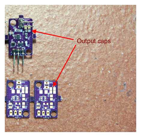
In the first assembly I put an output cap of 1uF to filter out some mid-frequency disturbance and reduce a bit the output ripple. An additional 100nF may be good as well.
Initial measurements
The controller is an Infineon ILD4001, and states a ripple of +/-15% in the current. With a setup at an Iset = 386 mA, I have measured the ripple, according to a sense resistor of 300 Ω. The upper current peak is 493 mA and the lower of 343 mA, with a delta of 32%.
Here how appears the current measurement the current ripple, measured across the sense resistor, in purple:
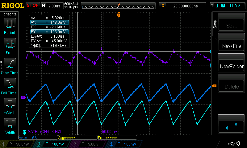
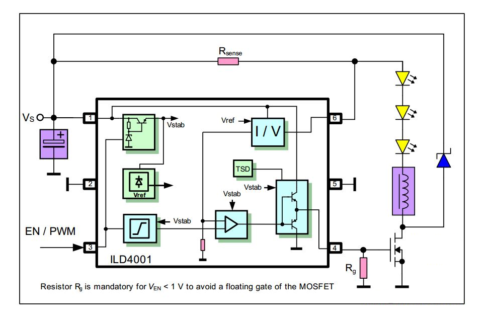
This is the overall current, which according to the following schematic, is the one flowing through Rsense:
To filter out the ripple, is needed to "steer" the AC component out of the LEDs, which translates in putting a parallel capacitor across them. If the LED has a given dynamic resistance according to its bias point and the capacitors a certain ESR, the (small signal) schematic looks like this:
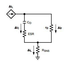
From which the current divider created let me find the ΔIf, and subsequently, from the equivalent capacitor impedance, finding an equation which provides the output ripple in function of the capacitor's impedance:
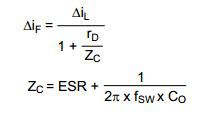
If the ΔIf reduced is, for example, from +/-15% of the initial to +/-2.5%, from the above formula:

Where Rd = 0.35Ω and the ΔIf−reduced in this use case is +/-25 mA. So, with an original 30% of ripple (+/-15%), to go down to 5% I needed at least 7.2uF.
Two low cost MLCC 0805 4.7 uF, 50V capacitors in the two available slots will do the job in all the LED configurations. Again, I did not put them (for now is the standard BOM) since it may never be an issue. But the user has the freedom to tweak it and here I just gave some suggestions.
 Enrico
Discussions
Become a Hackaday.io Member
Create an account to leave a comment. Already have an account? Log In.