Some basic definitions and a single phase test. PoC.
/*   3 half bridges made of complementary FETs, all gates are driven by MCU
 *   high sides are off when corresponding MCU pins are high
 *   low sides are off when corresponding MCU pins are low
 *   3 phase motor connected to half bridge outputs
 *   these outputs are also connected to MCU analog pins to provide voltage feedback
 */


#define PAH PB7   //phase A high side
#define PAL PB14  //phase A low side
#define PBH PB6   //phase B high side
#define PBL PB13  //phase B low side
#define PCH PB5   //phase C high side
#define PCL PB12  //phase C low side
#define PAF PA0   //phase A feedback
#define PBF PA1   //phase B feedback
#define PCF PA2   //phase C feedback

int fba, fbb, fbc;

void setup() {
  pinMode(PAH, OUTPUT);
  pinMode(PAL, OUTPUT);
  pinMode(PBH, OUTPUT);
  pinMode(PBL, OUTPUT);
  pinMode(PCH, OUTPUT);
  pinMode(PCL, OUTPUT);
  pinMode(PAF, INPUT_ANALOG);
  pinMode(PBF, INPUT_ANALOG);
  pinMode(PCF, INPUT_ANALOG);
  //neutral, off state:
  digitalWrite(PAH, HIGH);
  digitalWrite(PAL, LOW);
  digitalWrite(PBH, HIGH);
  digitalWrite(PBL, LOW);
  digitalWrite(PCH, HIGH);
  digitalWrite(PCL, LOW);
}

void loop() {

  digitalWrite(PAL, HIGH);  //drive phase A low (turn on low side transistor)
  digitalWrite(PBH, LOW);   //drive phase B high (turn on high side transistor)
  fba = analogRead(PCF);     //read feedback voltage
  //delay(1);
  digitalWrite(PBH, HIGH);  //drive phase B low (turn off high side transistor)
  delay(10);

  Serial.println(fba);
}


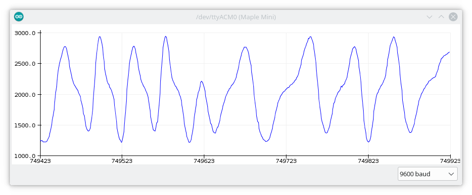
As seen on the first graph, some noise is present when the rotor is not moving but, as you can see on the second one, the signal-noise ratio is very good. The signal slope is not even. Some regions have steeper slopes than others. On the second graph, the section from the start to the valley bottom represents an almost constant velocity. The varying slope is the product of the physical construction of the motor. Here I tried to spin it slowly but evenly with a sudden direction change at around 749623:
If you change the delays in the code, you can change the sampling frequency and the on-off ratio. With more on-time the rotor wants to stay in a certain position. That is basically a method for haptic feedback.
Discussions
Become a Hackaday.io Member
Create an account to leave a comment. Already have an account? Log In.