So, my sophisticated method for analyzing the results was to draw lines over the screenshots in paint. And on paper with a pencil. :-) Just to understand the data well enough.
Conclusions:
- The sensor data comes in 3 pairs. Mirrored to each other. Simply because I measure all sets twice, with opposite polarity. We can select 3 to work with in operation.
- The period of the sensed signal is half of the drive signal. The motor has 6 steps in one magnetic cycle (my motor has 4 cycles, 30 steps/revolution) and the sensed signal repeats after 3 steps. That can be a problem with haptic feedback. When you switch it on the first time, the controller doesn't know in which half of the magnetic cycle the motor is. That can cause a bigger than normal jump of the rotor, and missed or false steps. Not catastrophic, but inconvenient. It can be moderated if the high current drive is ramped up with PWM.
- In my opinion, the easiest way to detect a movement is to store the last step, and measure one signal of the selected 3.
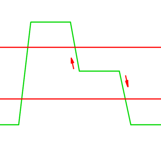
In every "clean" step, one of them is at center position, in my case that means an ADC result of 2000 - 2150. The high position can reach 2800, low 1300. (Due to laziness, I only noted one channel.) selecting threshold values is easy. If that channel is measured, which should be centered, and it goes up, that means a step in one direction, down is the other.![]()
Discussions
Become a Hackaday.io Member
Create an account to leave a comment. Already have an account? Log In.