 Mattia Dal Ben
"There are no strings on me..."
It's now almost a year that I'm working on and off on the Redox project, however I keep asking myself: "How can I improve this design further?".
"Wireless" is the answer.
In the last few months I began researching how to make a split QMK-compatible keyboard wireless and the only answer was the Core51822(b) module (see the Mitosis for further details. On a side note: that keyboard is awesome!). Needless to say I ordered a few immediately and began experimenting.
Receiver
I began by replicating the receiver module using the available schematics from the Mitosis project.
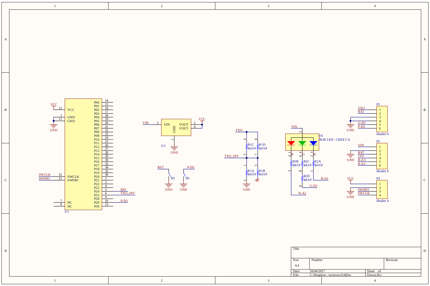
I used a breadboard compatible version of the AMS1117 3.3 voltage regulator to power the Core51822 and for the remaining parts I used through-hole components I had laying around. I then realized the main drawback of using the Core51822: those damn 2.0mm pitch headers. I got a little creative with the hand soldering but for the keyboard matrix wiring I'll use some 2.0mm pitch to 2.54mm pitch jumpers I found on Amazon.
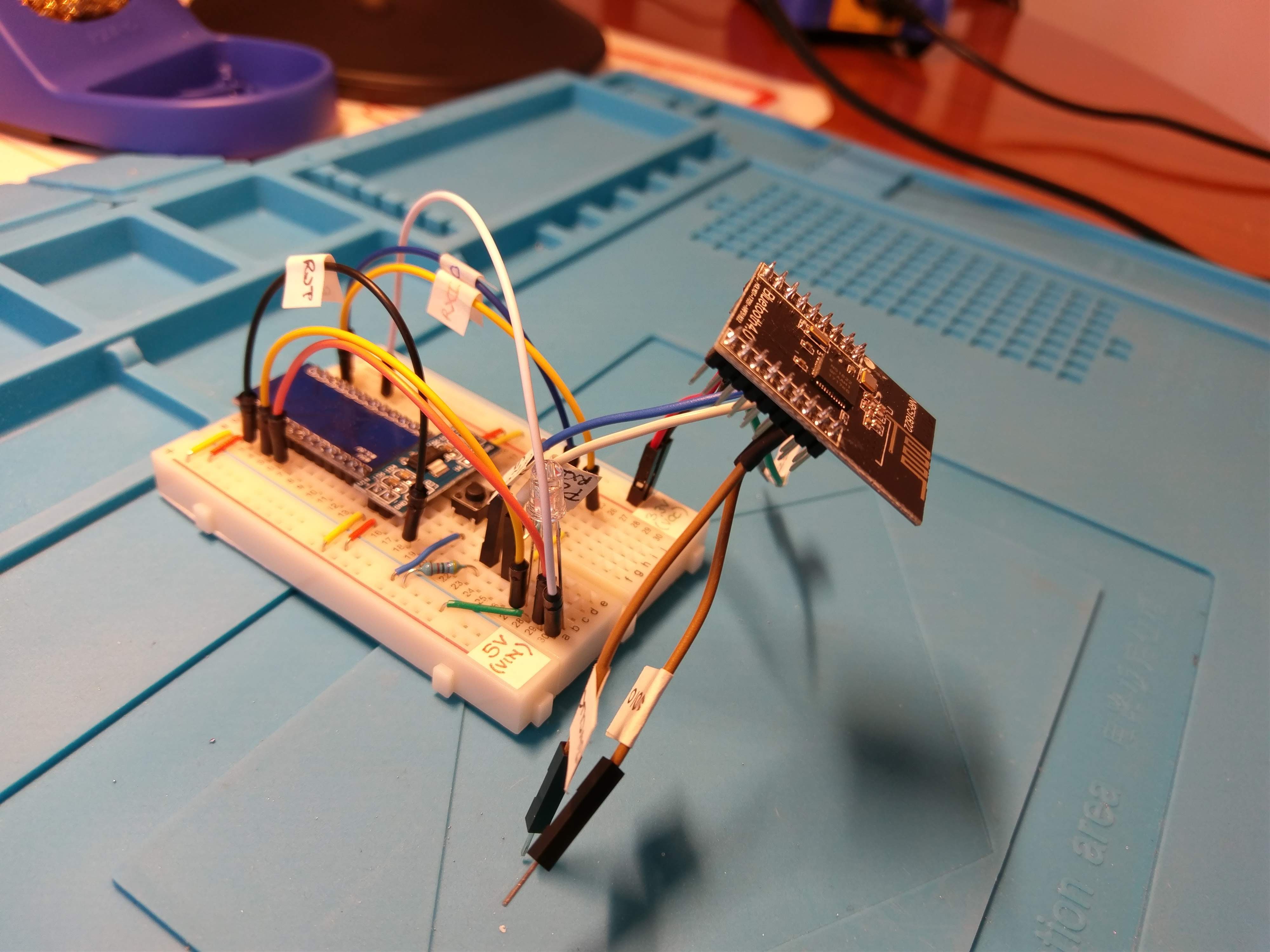
I then tested that everything was working with the usual led blink. To get to this point I used this excellent guide for the NRF51822.

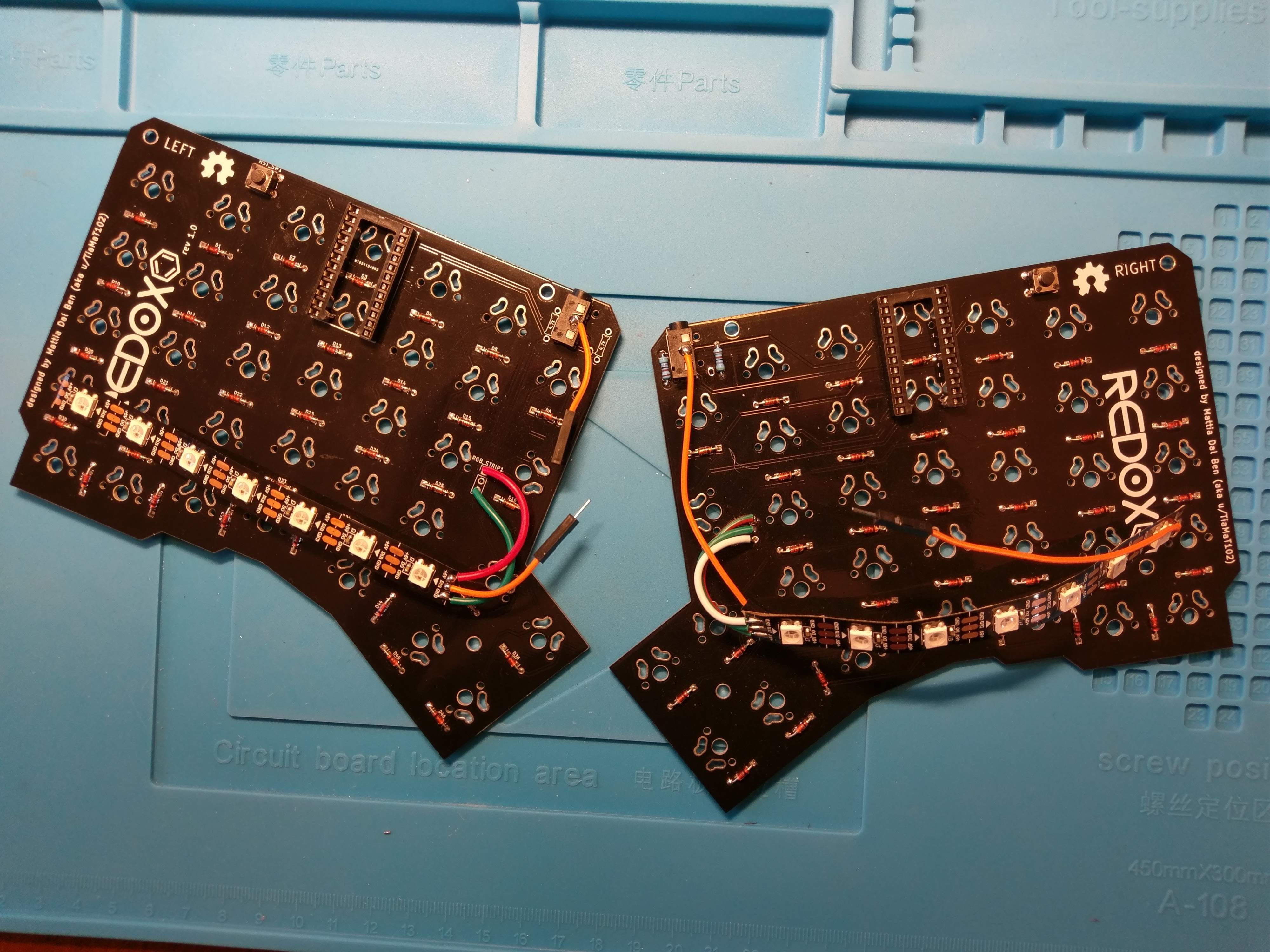
Now it was time to wire the keyboard.
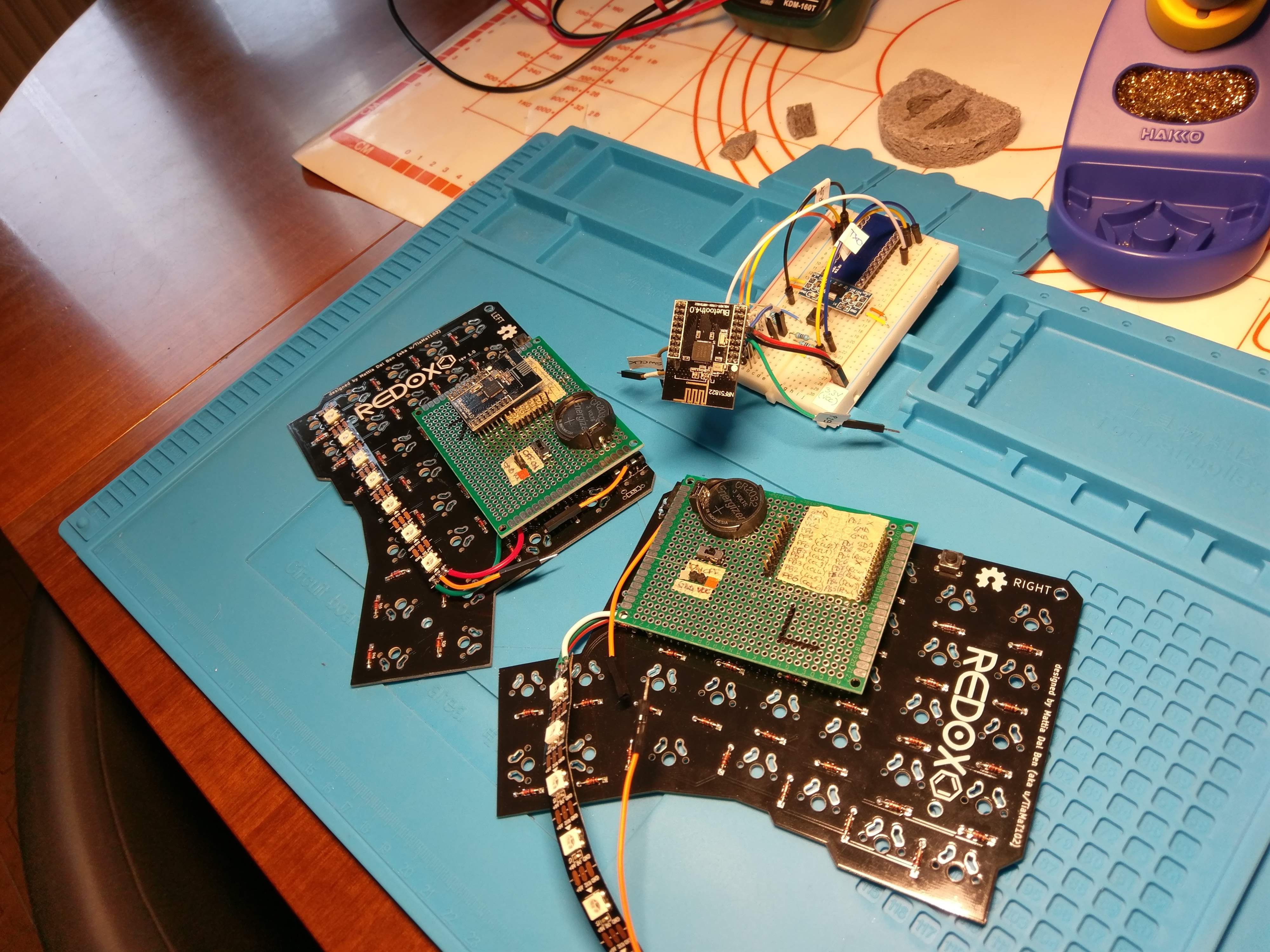
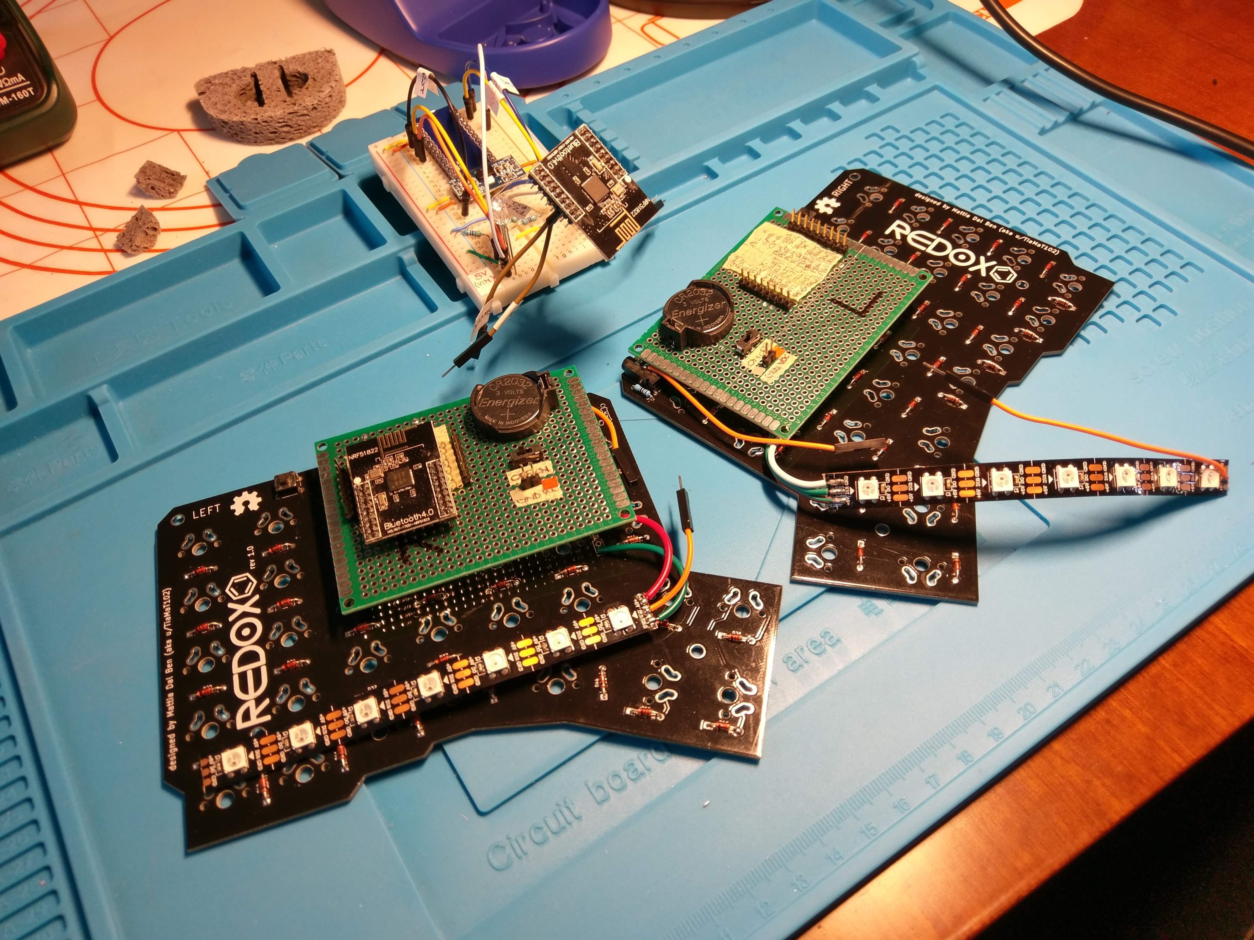
Transmitters
Since this is just a proof-of-concept I wanted to recycle my testing board before designing a new PCB from the ground up.
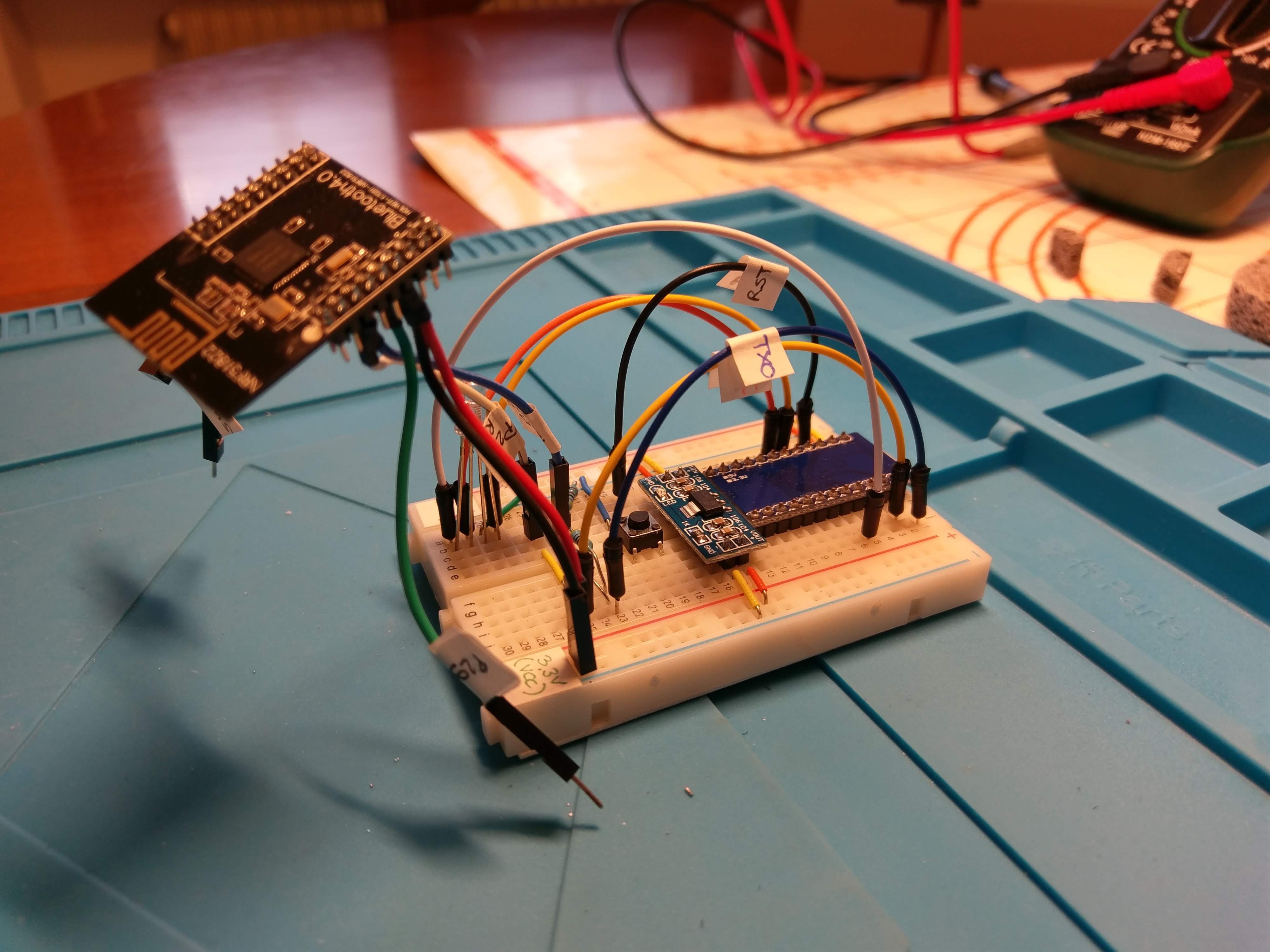
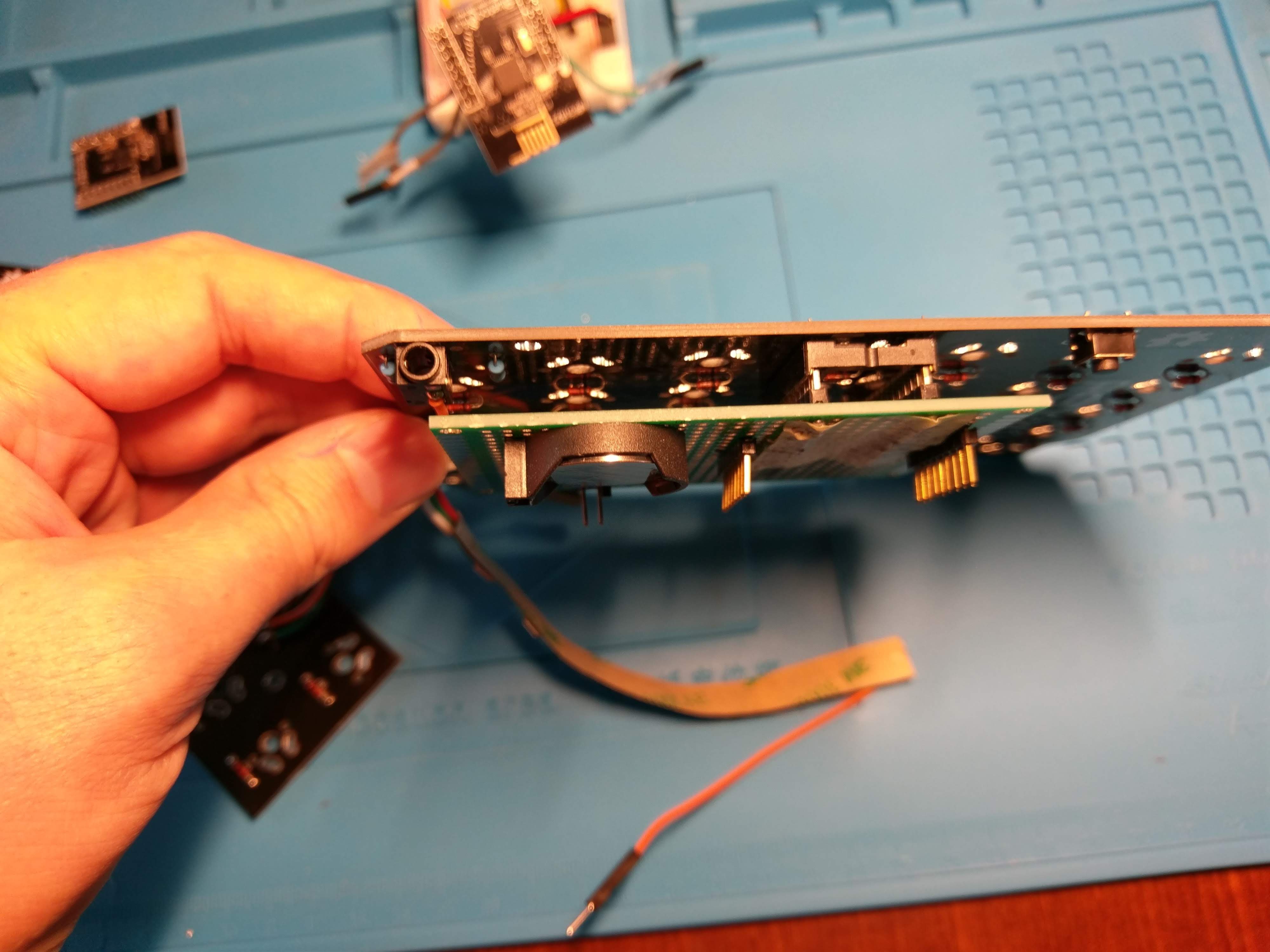
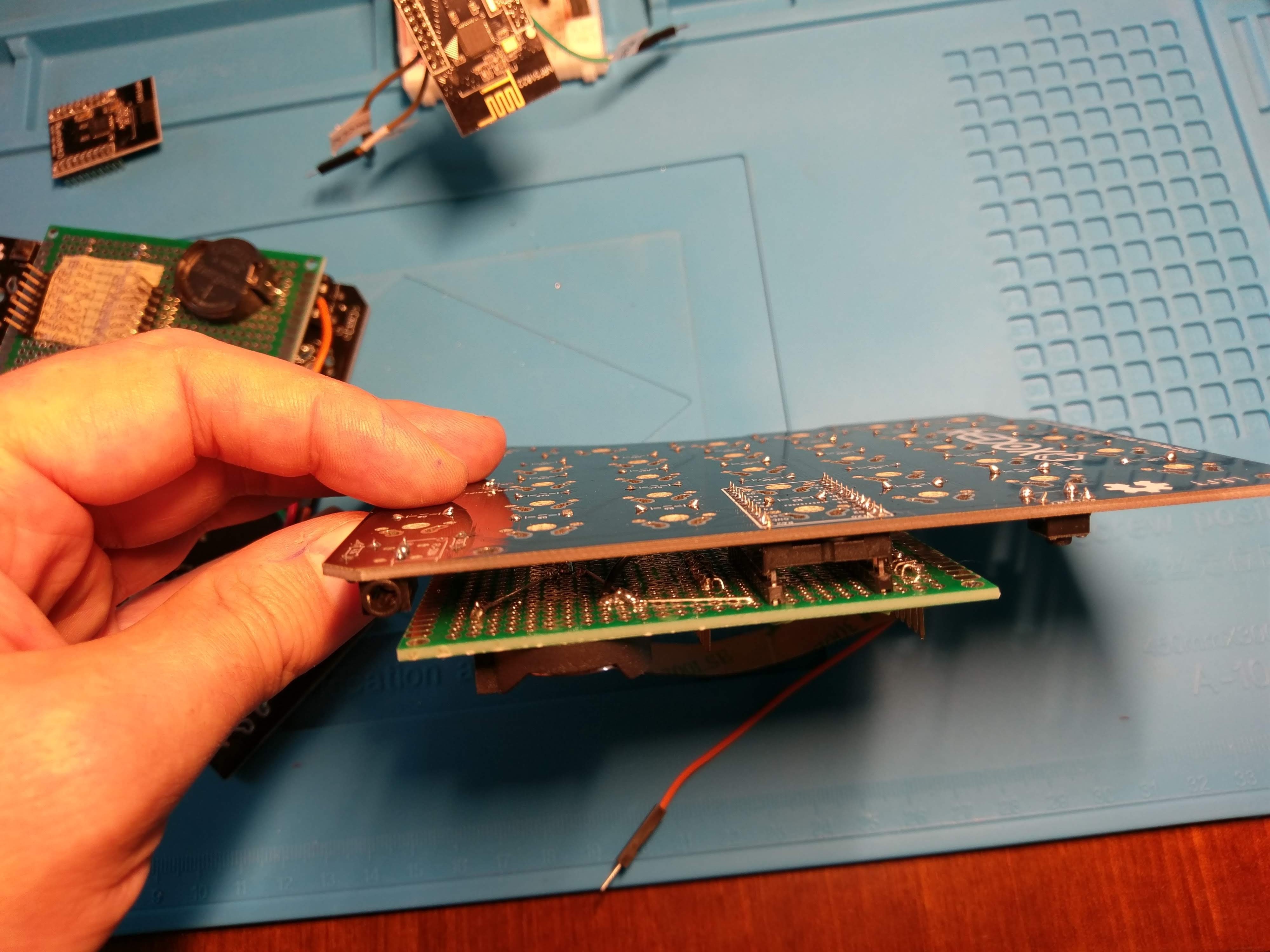
I then decided to create a sort of adapter for the Arduino Pro Micro to something that can be wired to the Core51822. I came up with the following:
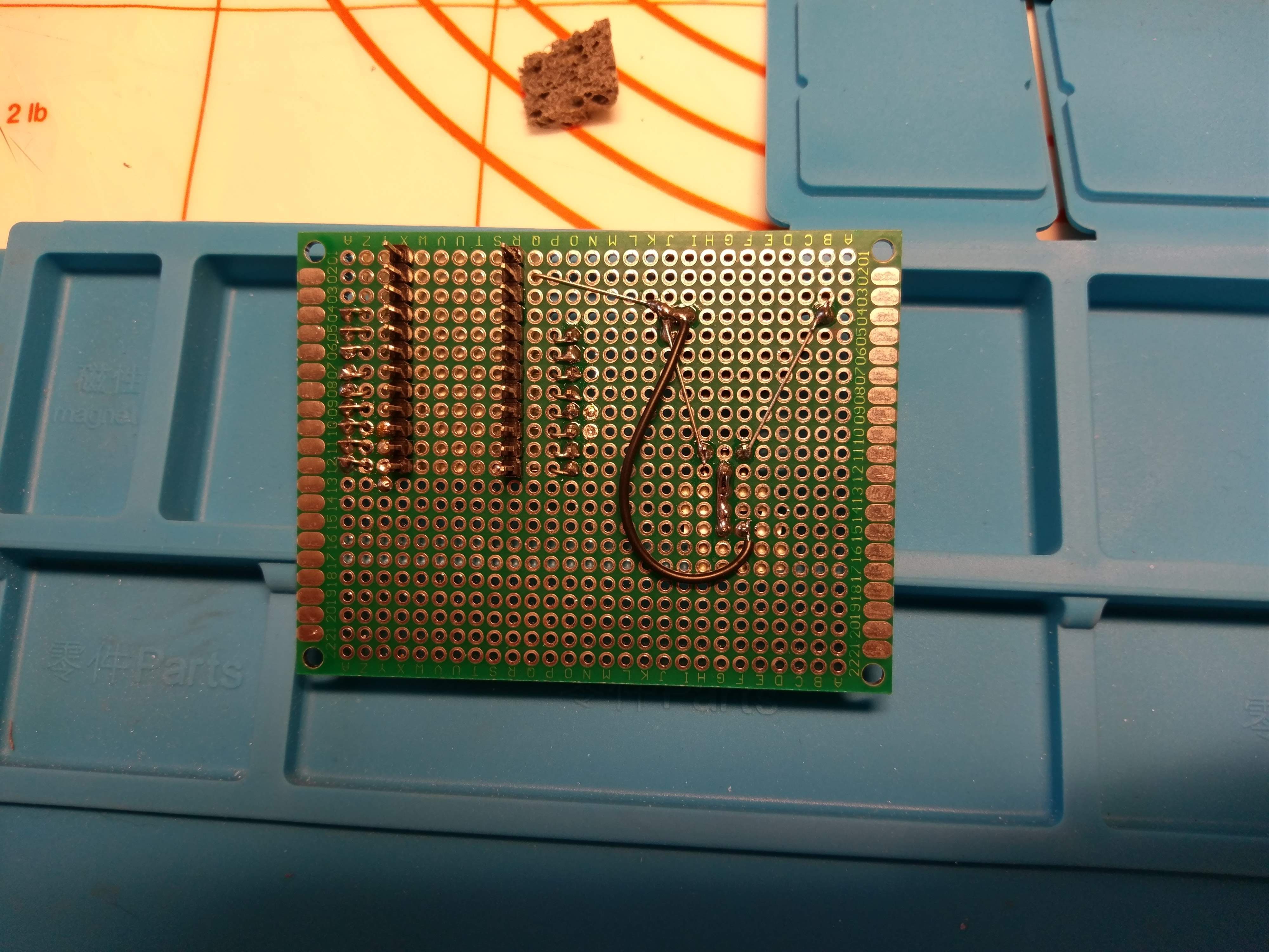
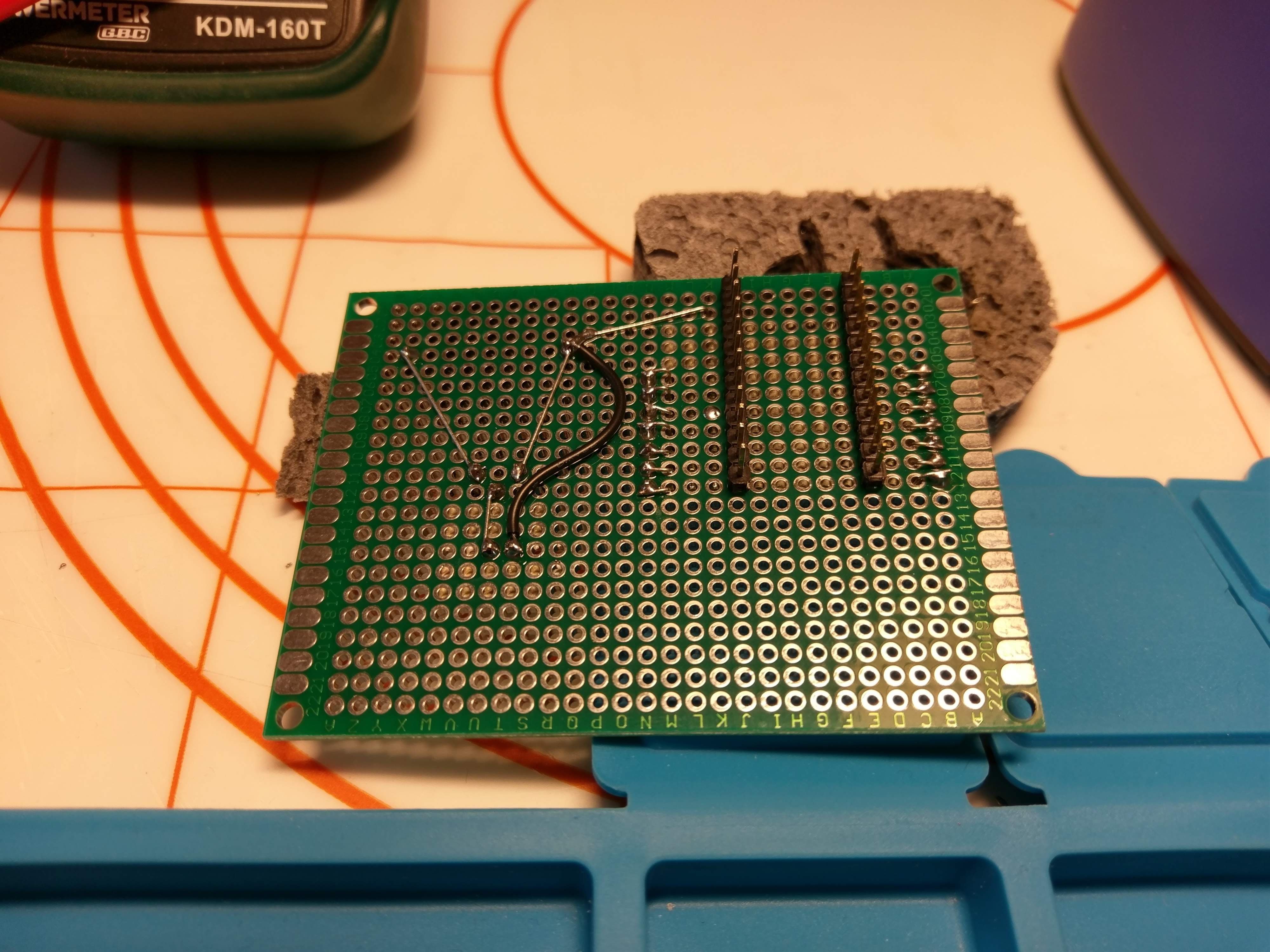
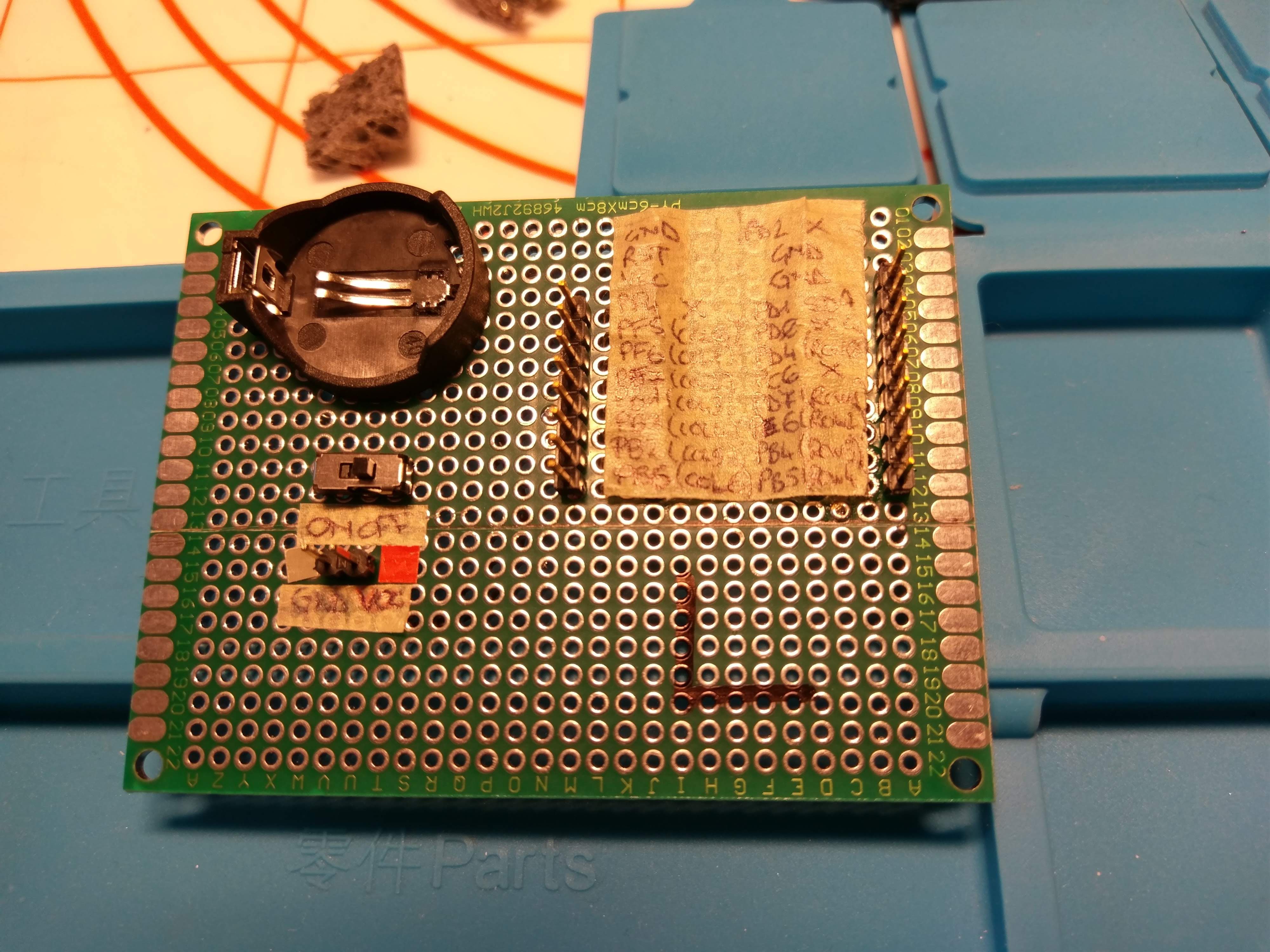
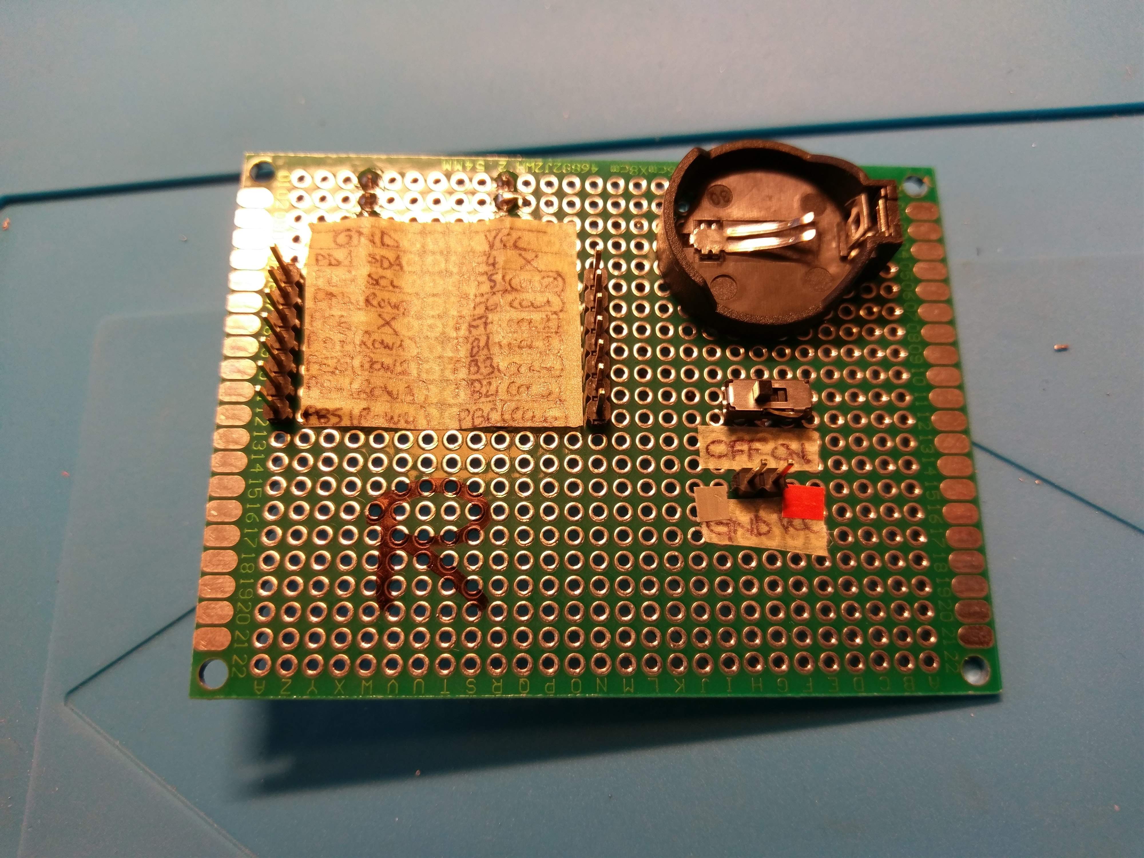
I have a pin header row that fits inside the Pro Micro footprint, those pin are then wired to another row of pin headers that will be connected to the Core51822. I used a CR2032 to power the module.
 I am now waiting for the jumper cable to arrive to finally get writing some code. Once I get everything to work I'll begin designing the new PCB... my main goal is to make them compatible with the existing cases but I think this will not be an easy task.
Discussions
Become a Hackaday.io Member
Create an account to leave a comment. Already have an account? Log In.