 Mattia Dal Ben
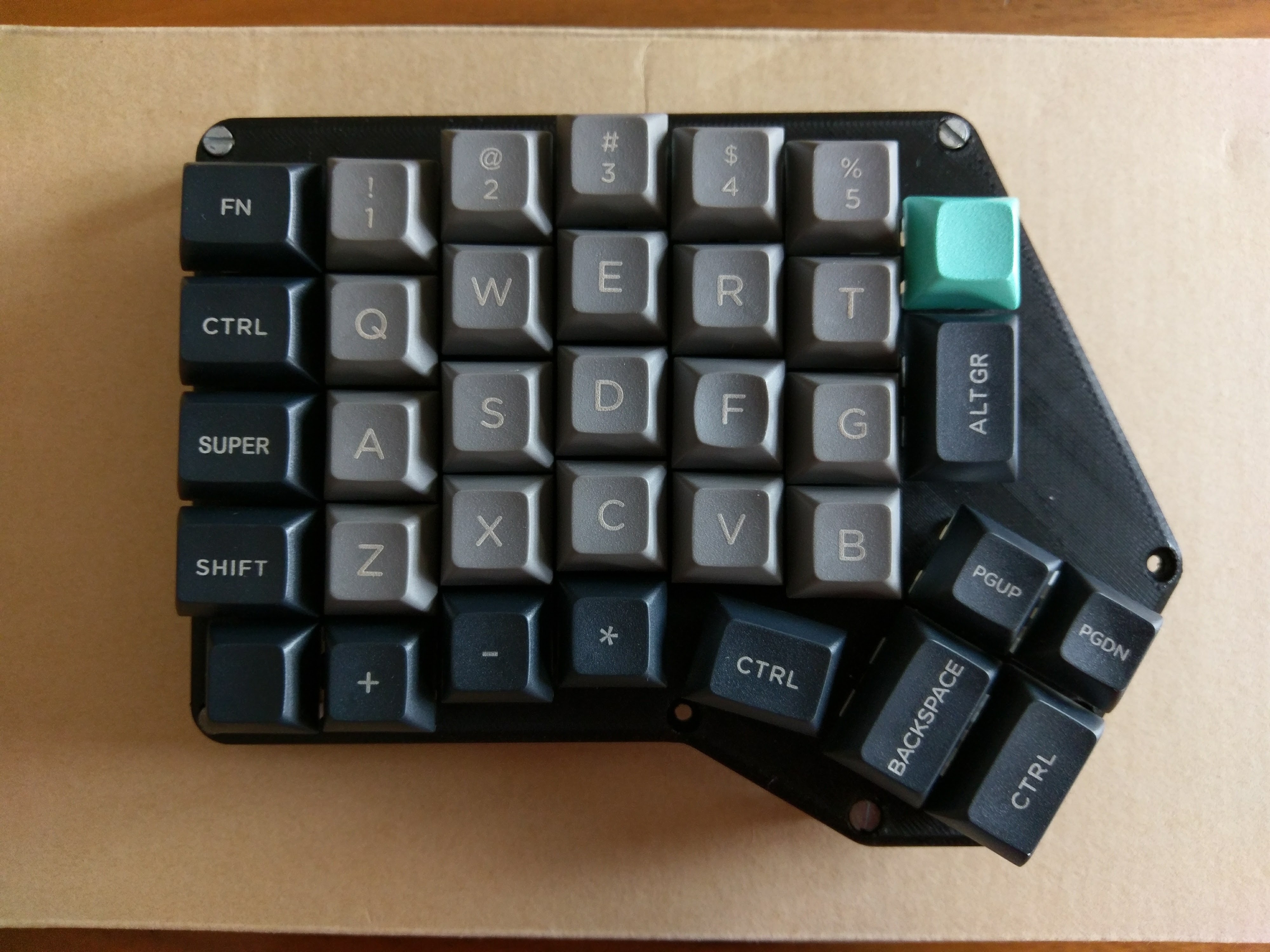
This was the first prototype for the Redox project. At the time I wanted only to test the ergonomics of the idea so I opted for a handwire.
Materials used:
- 70x: Cherry switches
- 70x: Diodes (I used 1N4148)
- 70x: Cherry compatible keycaps
- 10x (8x for 1u Layout): 1.25u keycaps
- 6x: 1.5u keycaps
- 54x (56x for 1u Layout): 1u keycaps
- 14x: M3 8mm screws
- 2x: 4 poles 3.5 mm panel mount plugs
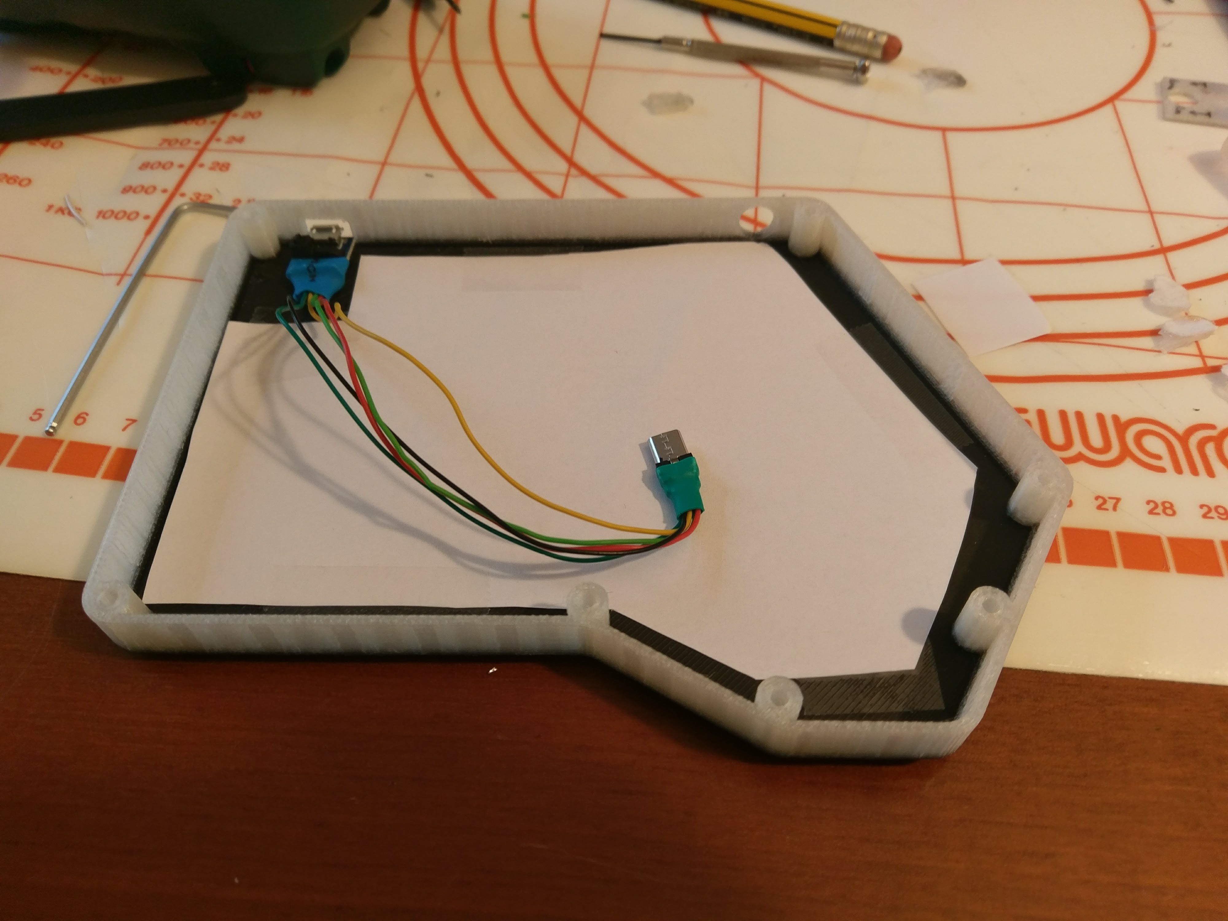
- 2x: Arduino pro micros (Atmega32u4)
- 2x: USB micro male to female cable/adapter
- 2x: 3D printed cases
I started with the plate design. I 3D printed it and built my first mock-up. This was just for testing tolerances and checking that everything was fine (and cool looking).
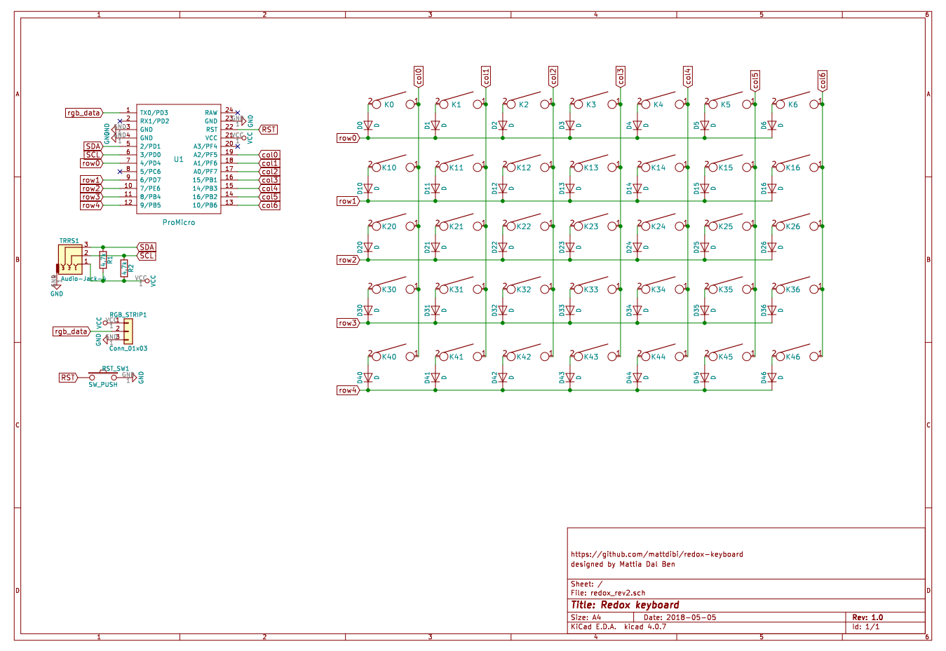
Then it was time to some proper planning for the handwiring. I started with a schematic then moved with the wiring planning on paper (it was easier this way).
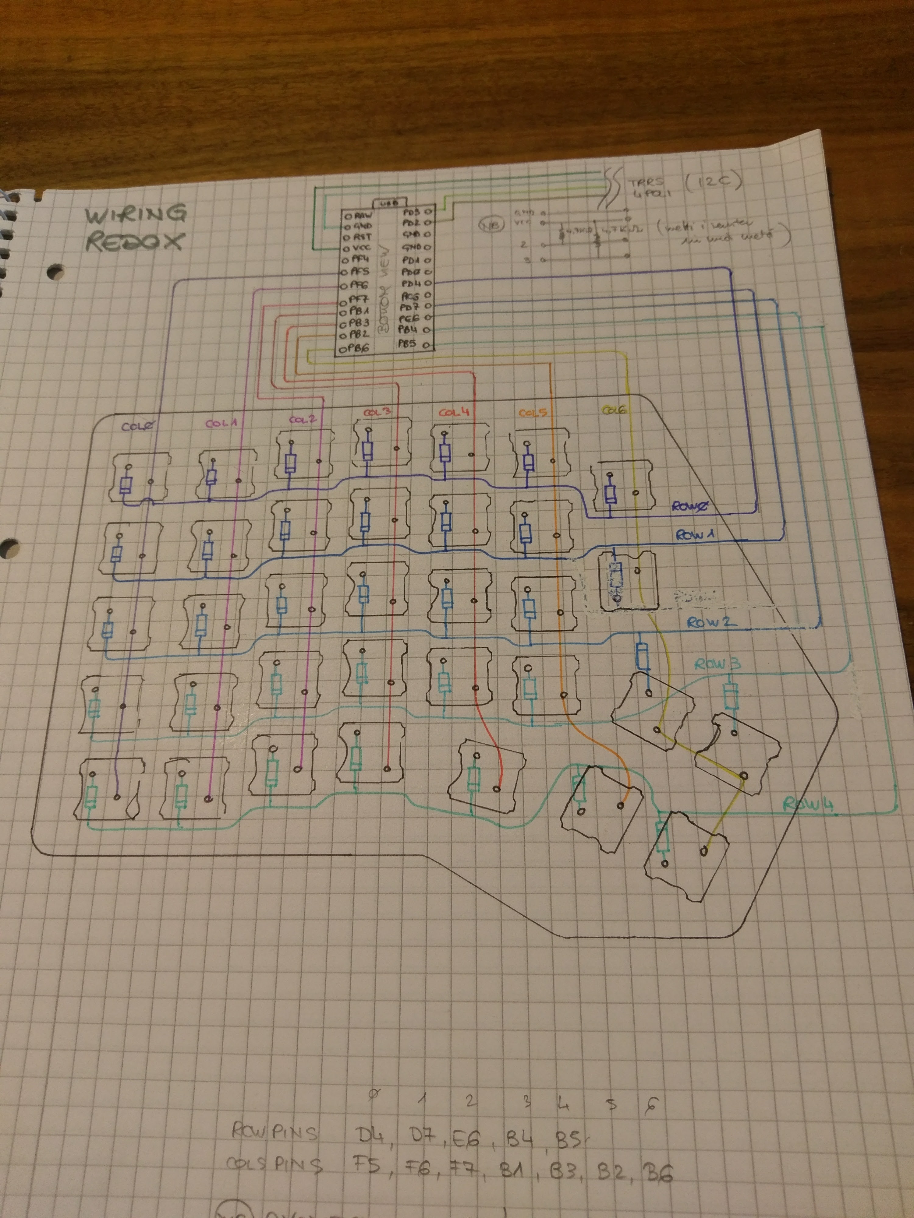
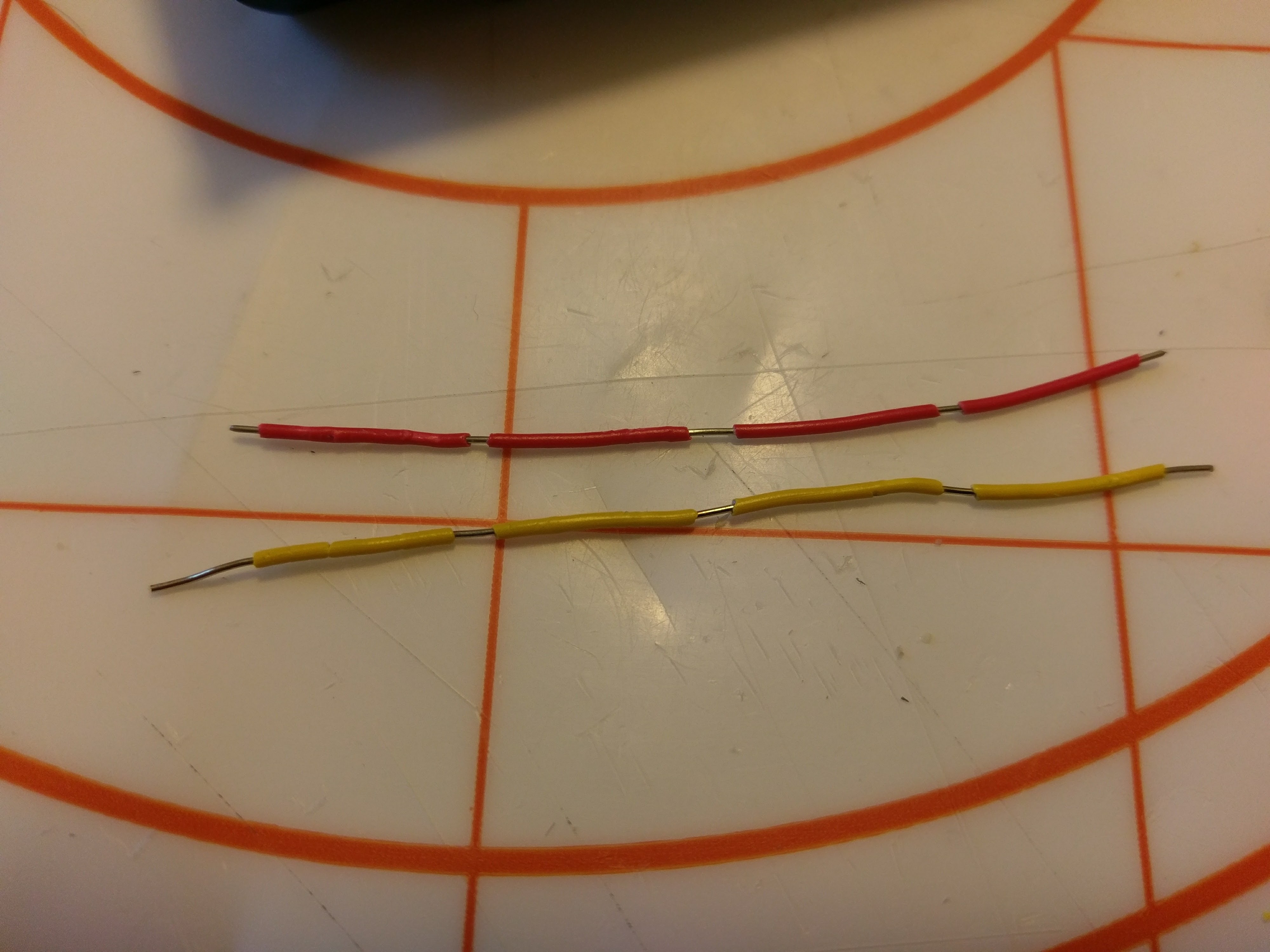
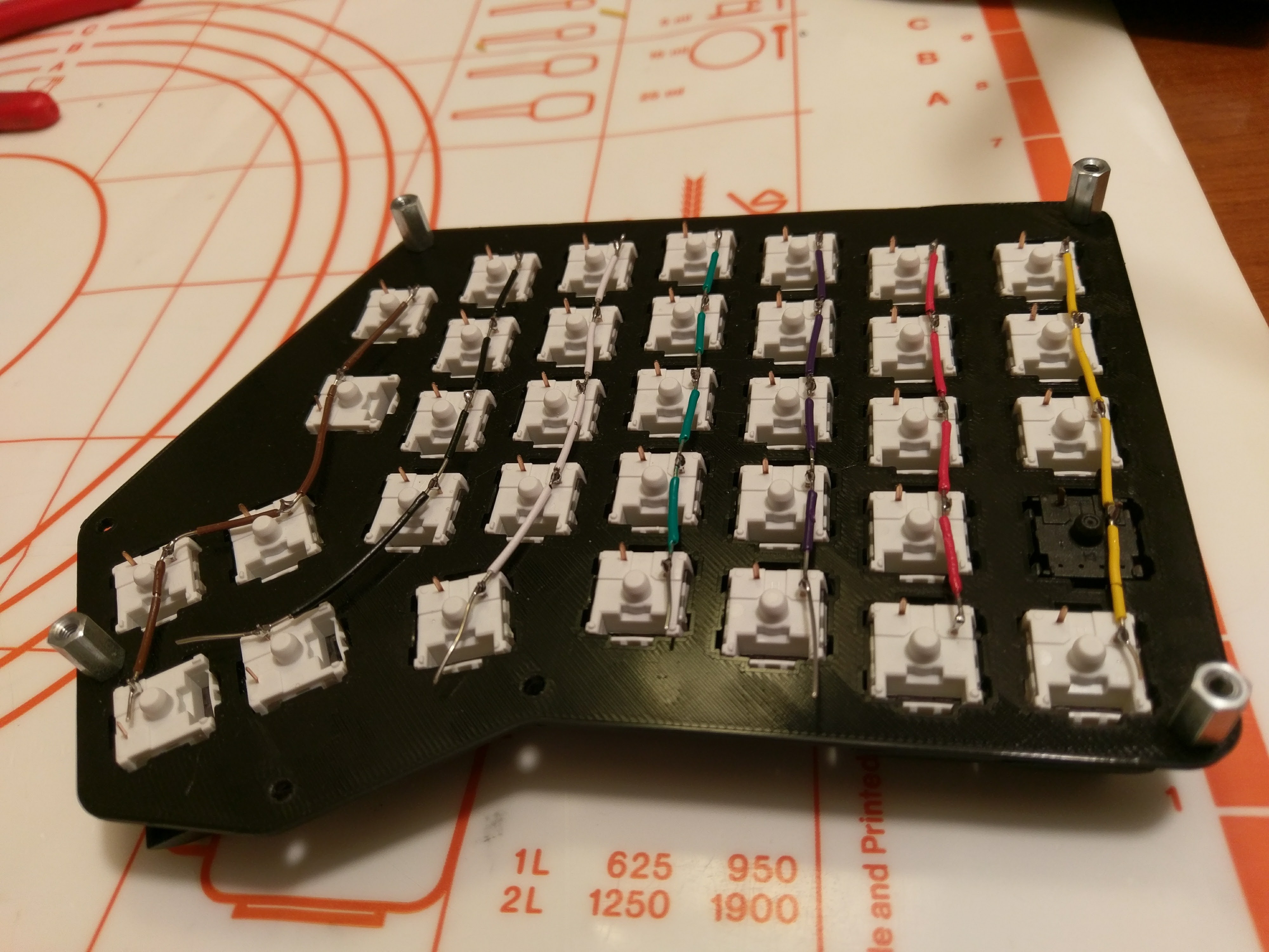
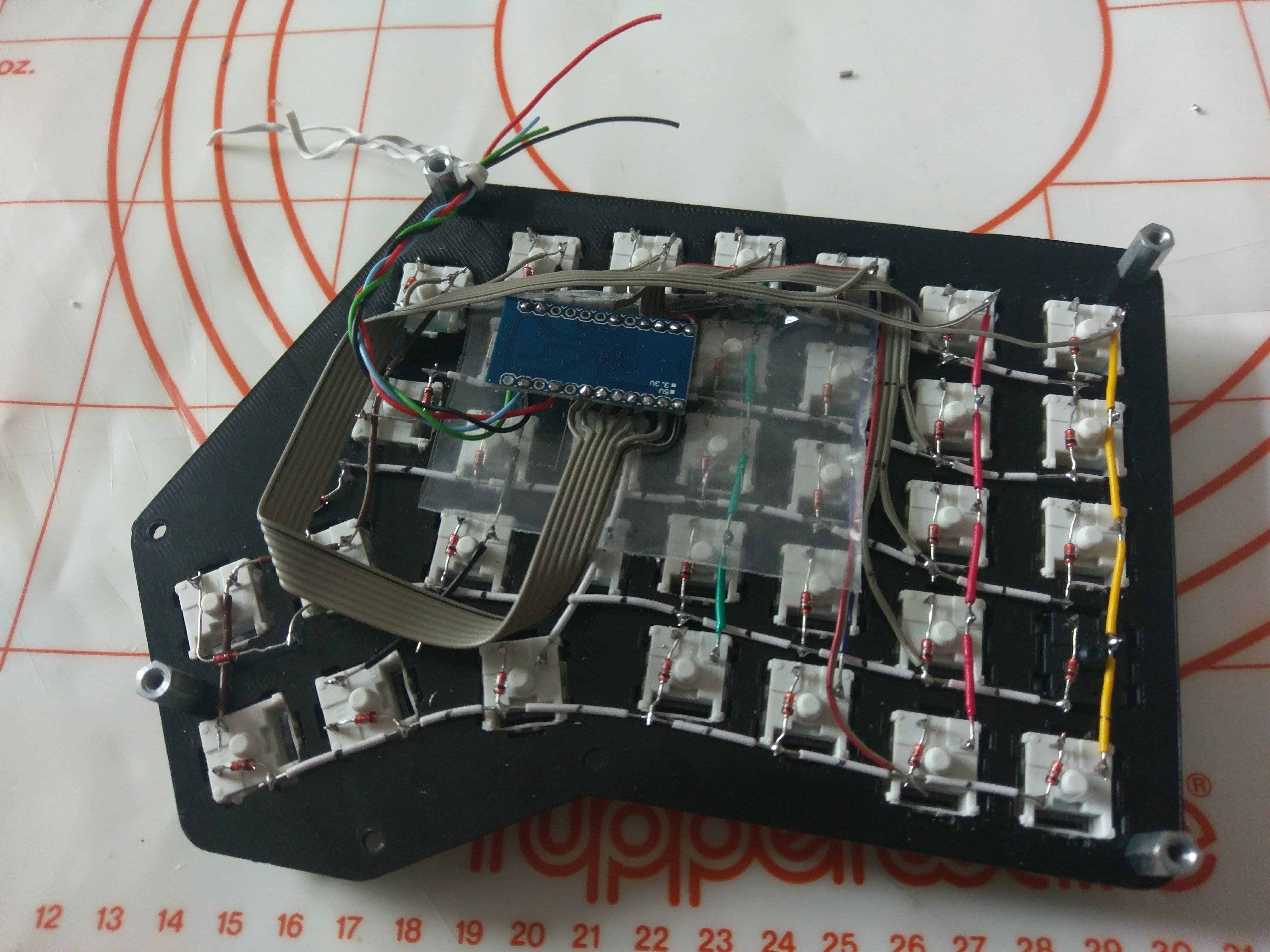
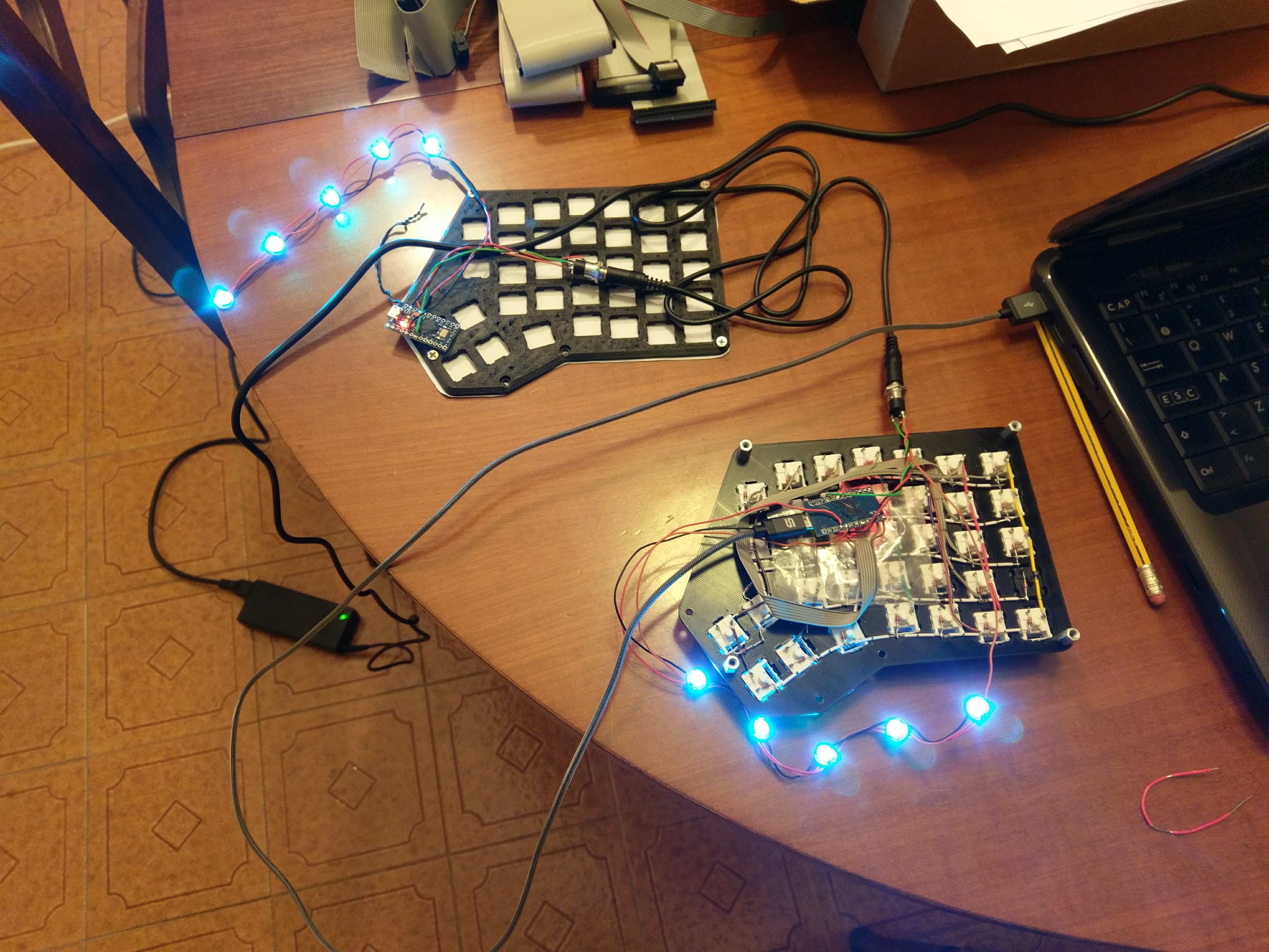
Finally I started soldering. My technique involves stripping the single-core wires so that the inner core is exposed at the height of the switch pin. Then I use the rigidity of the wire to make it stick to the pins alterinating the side which makes contact with the pin.
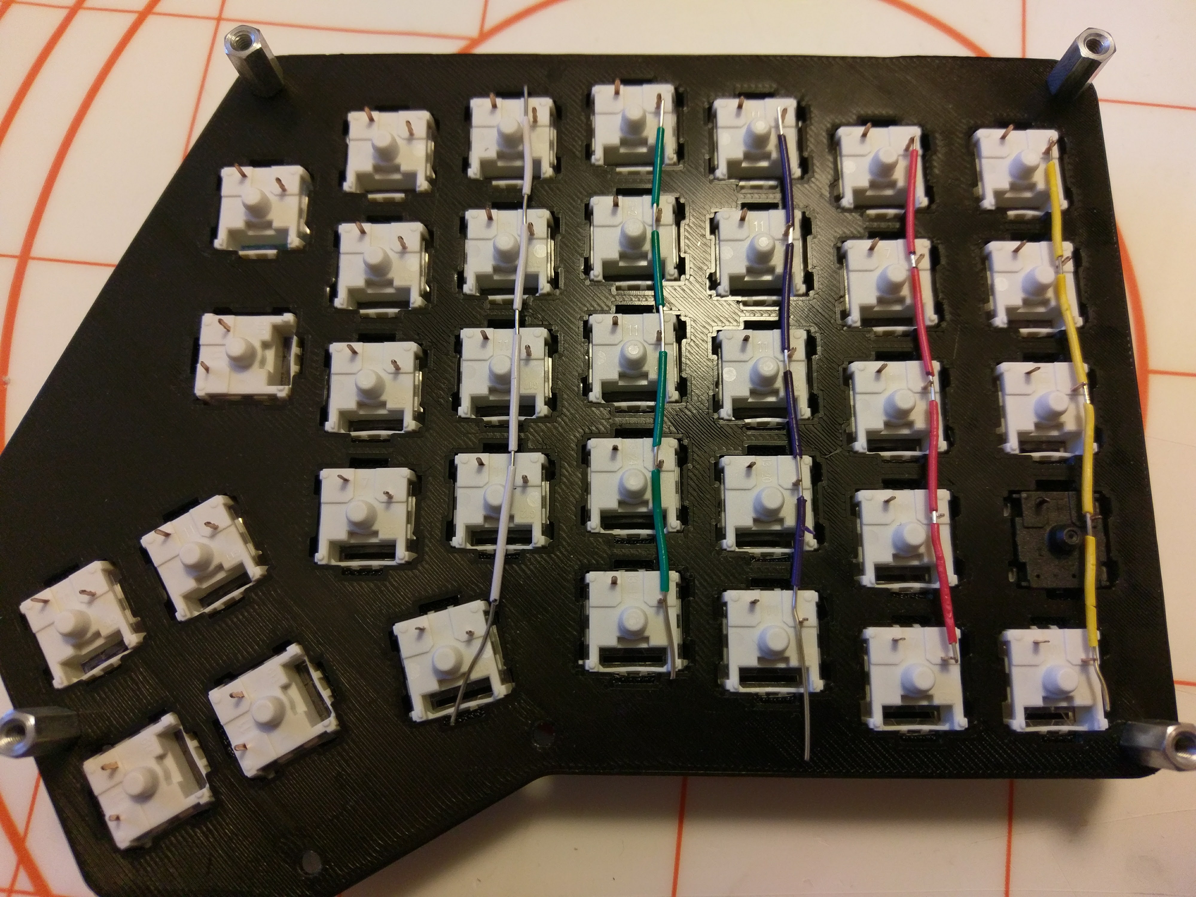
The it was a simple matter of patience and time...
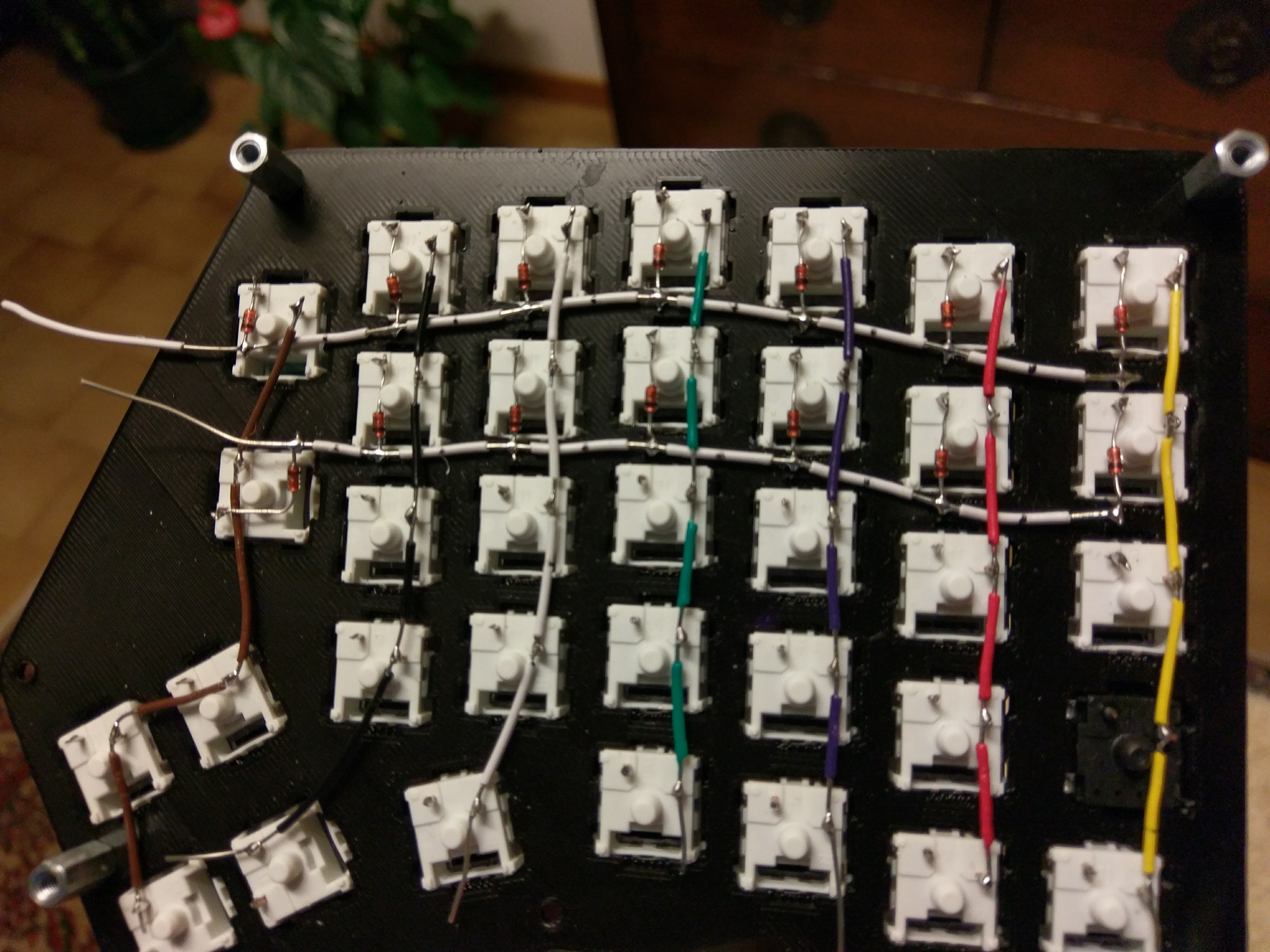
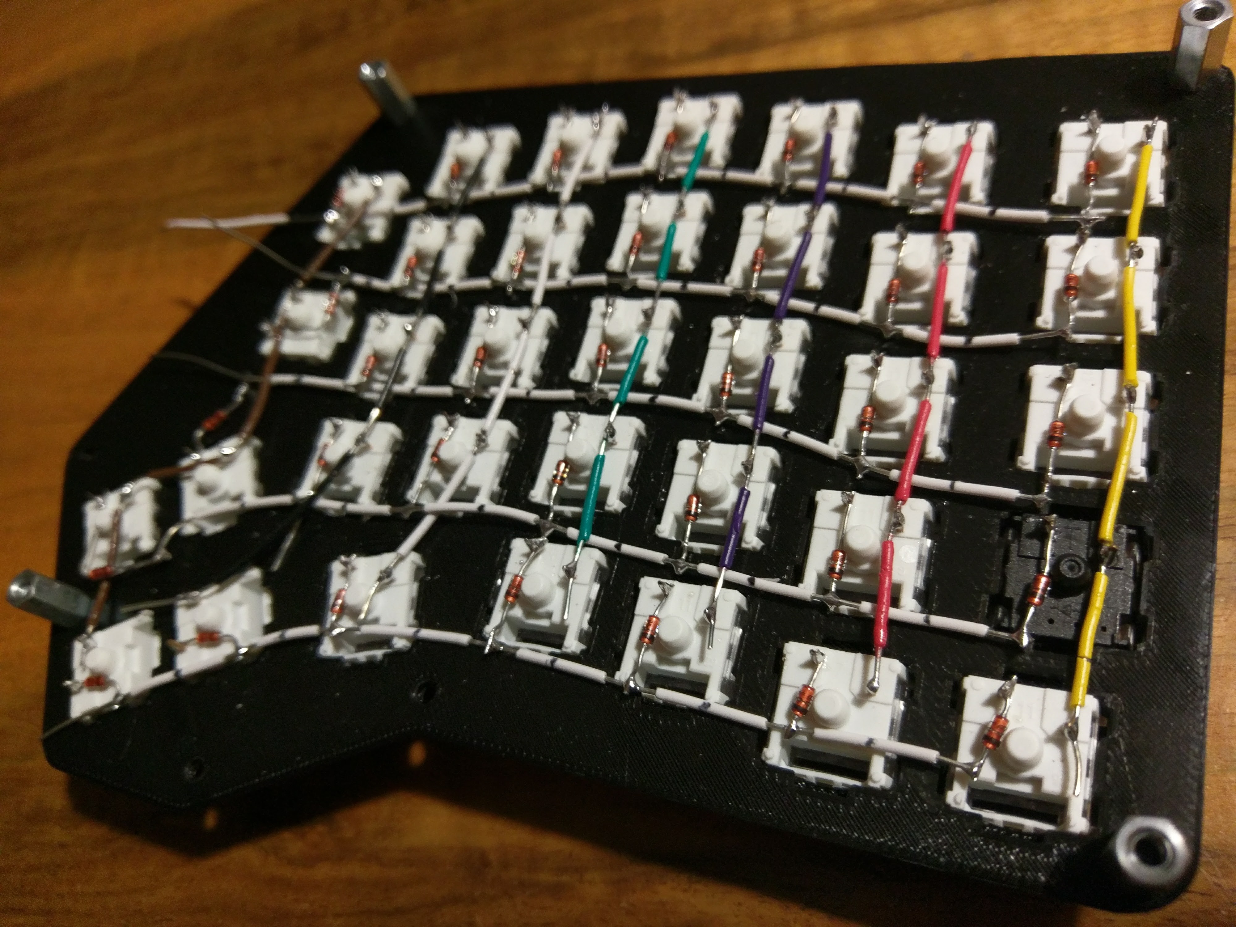
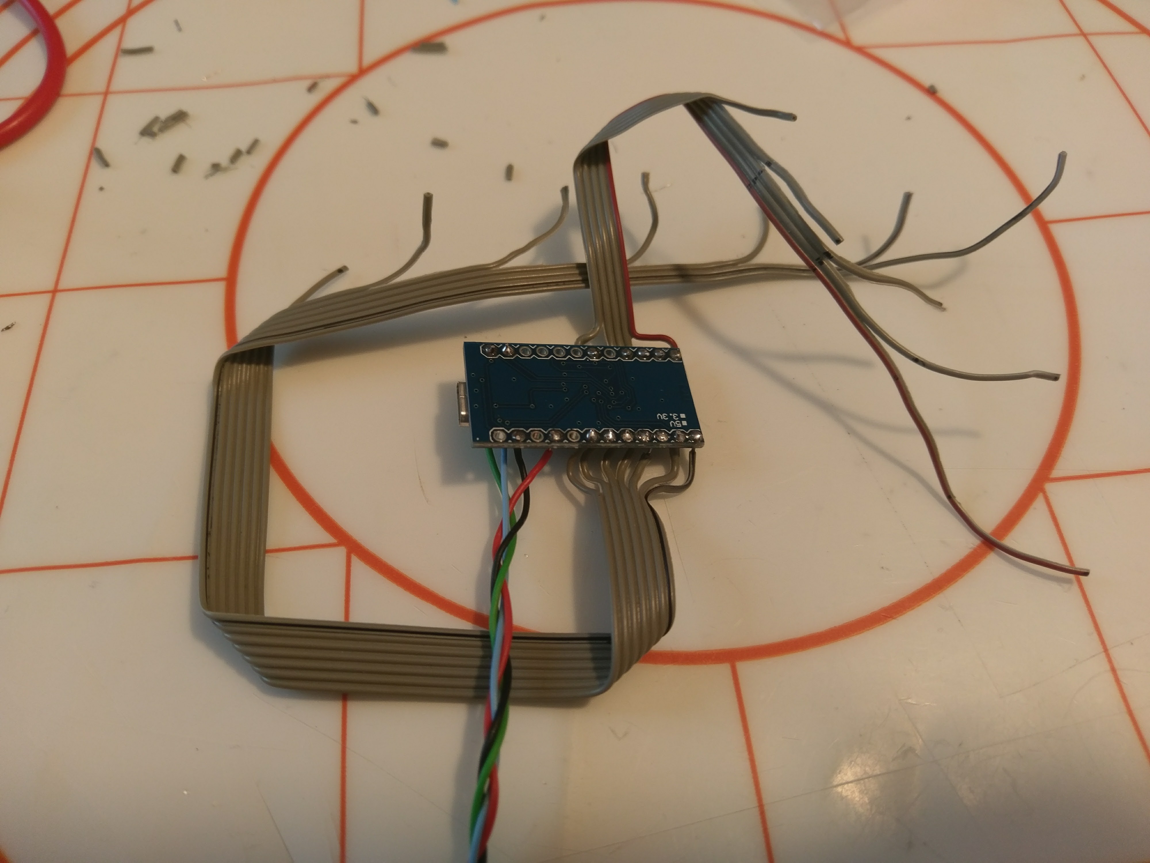
For wiring the controller I used some old IDE cables I had laying around. This helped a lot in cleaning the overall wiring mess.
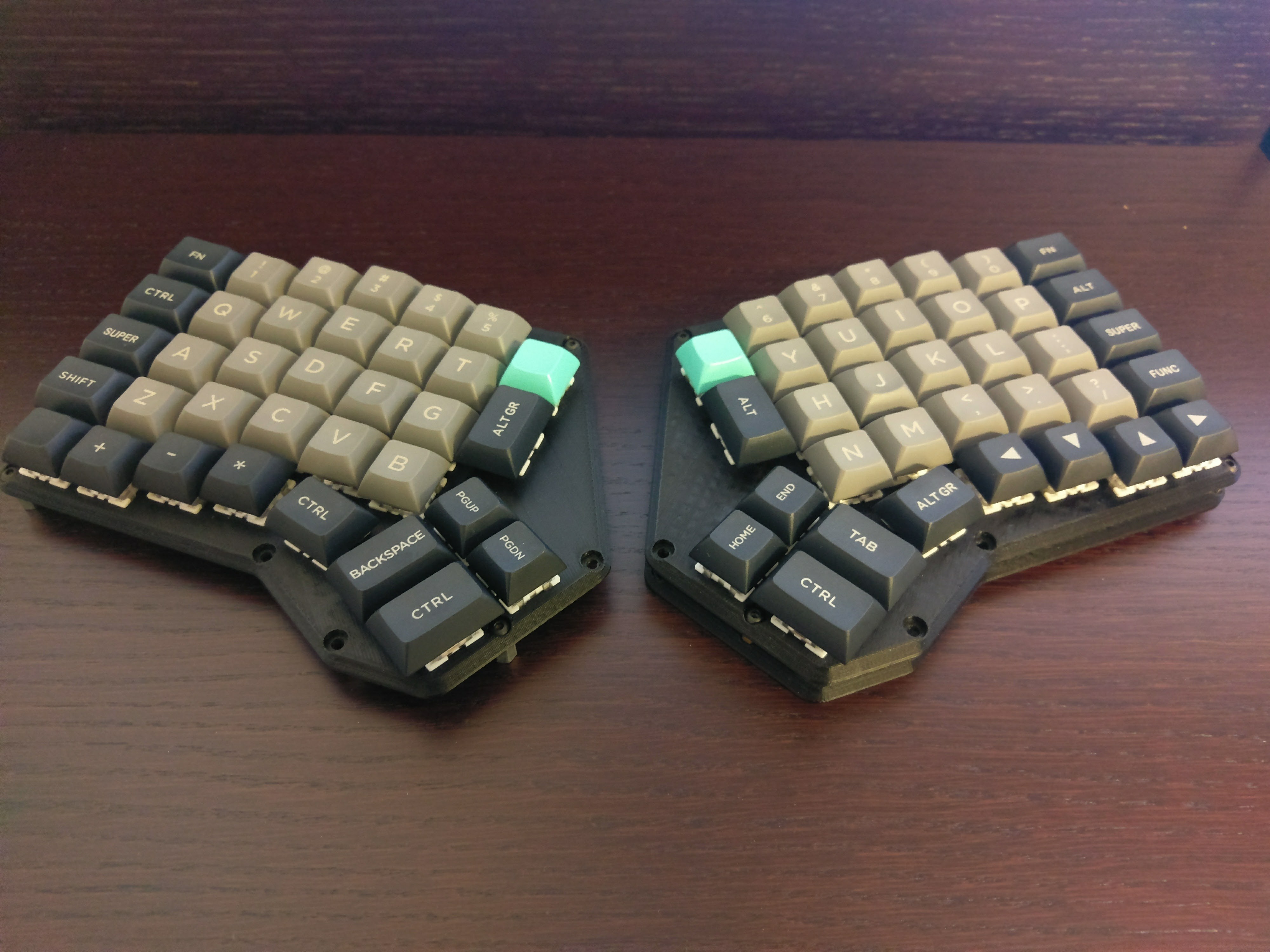
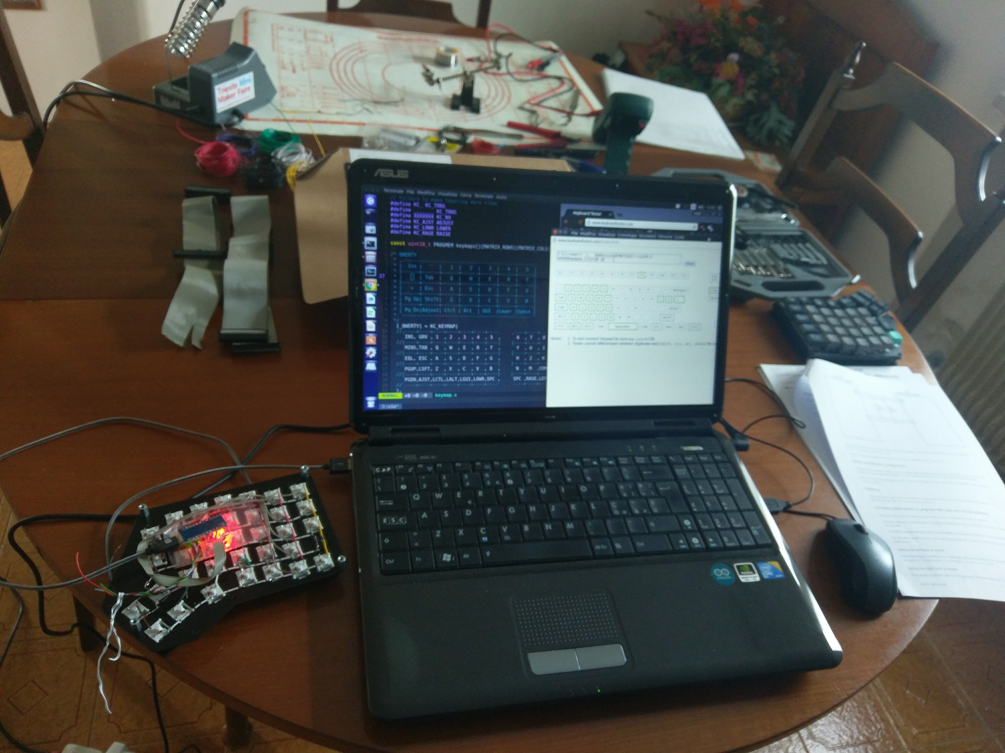
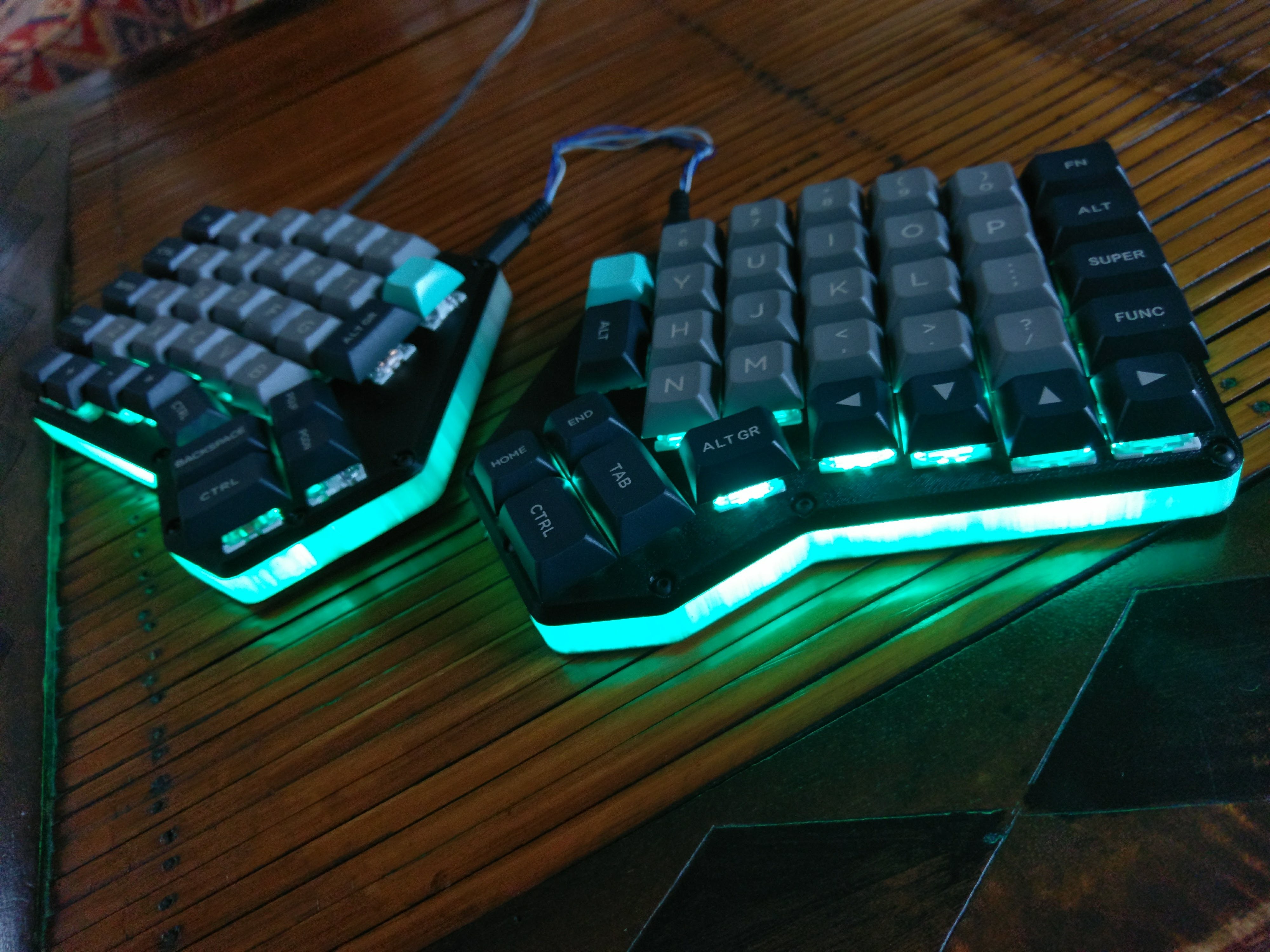
Programming time. I based my keymap off of the Viterbi keyboard since it has the same number of keys. This way I sped up the testing phase.
I then added some LED backlighting for good measure because why not.
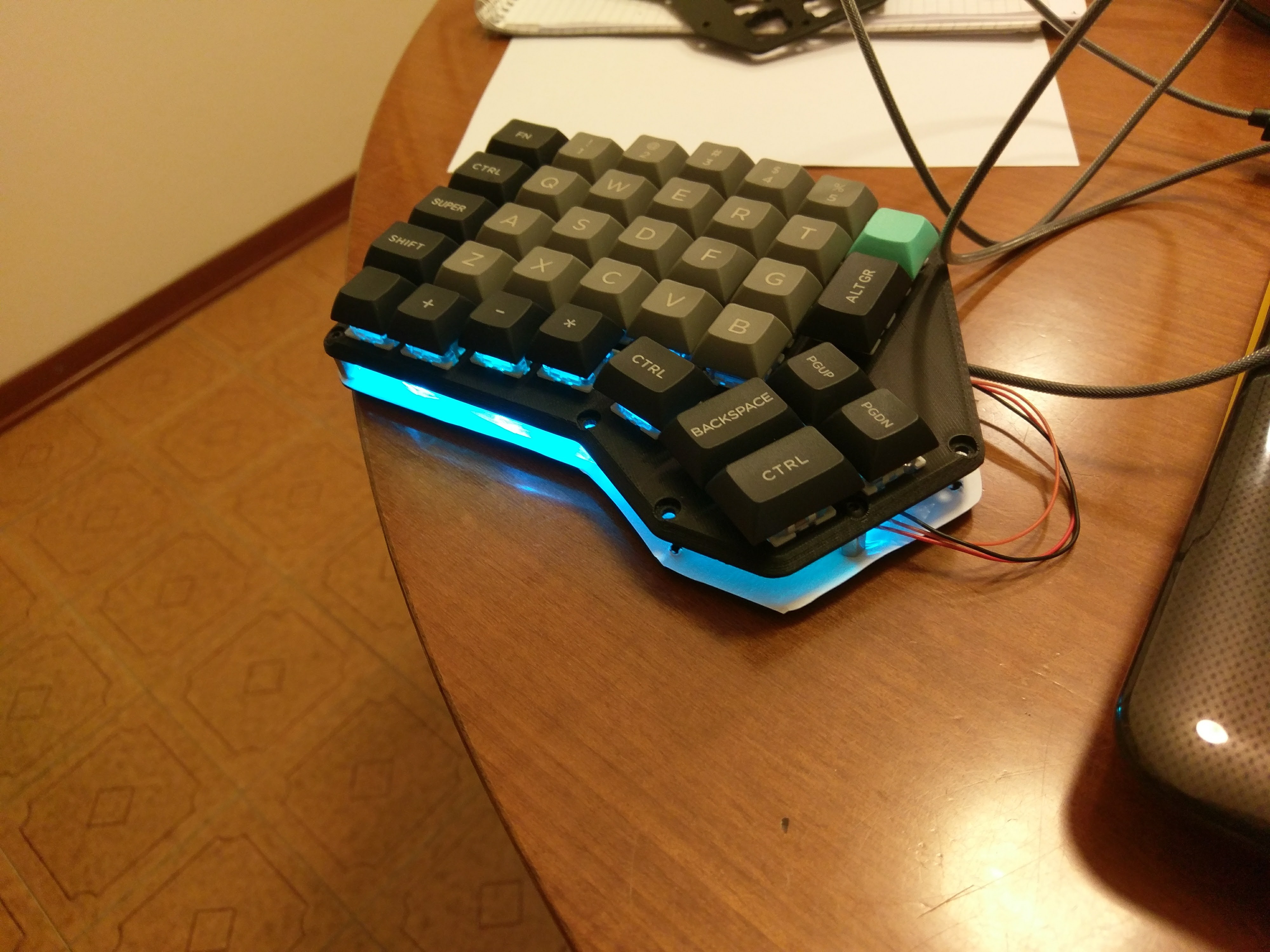
Finally I printed the bottom half of the case and finished the prototype.
Since its publishing the Redox handwire gained a lot of attention and inspired some great designs:
- Tilted Redox case: tilted case for the Redox prototype by jschloer.
- couscous-kbd: Redox-inspired parametric OpenSCAD keyboard design.
- Redox tenting kit: modified base to support tenting, mini-USB for the interconnect, and a hole for microswitch for reset needed when uploading new firmware by Lenbok.
- Iris-inspired Redox case: a case inspired both by the Redox rev1.0 and the Iris designed with OpenSCAD by Lenbok.
Discussions
Become a Hackaday.io Member
Create an account to leave a comment. Already have an account? Log In.