 MakersBox
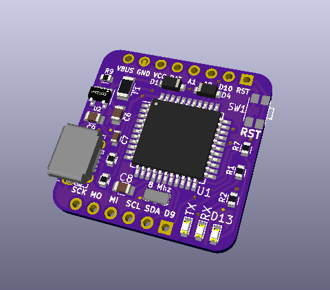
So again, for those commenters who didn’t read this far, I don’t think a 32U4 dev board is my gift to mankind. In fact, even copying Adafruit’s IstyBitsy straight into KiCAD is going to be at the limits of my ability. I like the IstyBitsy’s power management and reset button and the Pro Micro’s LEDs and polyfuse so I am going to fuse those together (pun intended).
The physical layout is actually pretty easy since I’ve got a defined board space and pin spacing. I want to make it so the bloks cannot be put in backward, so I’ll put eight pins on top row, six on the bottom row (wow, echos of Arduino here?). This will also allow us to use standard Arduino through headers if we start start stacking. We need:
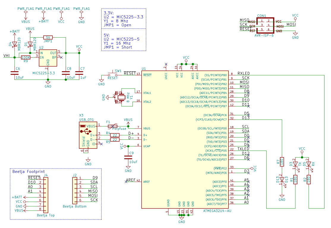
- Power: VBus (USB 5V), VCC (3.3V), Vbat, Gnd
- I2C: SDA, SCL
- SPI: MOSI, MISO, SCK
- Digital I/O: D9, D10 (both PWM)
- Analog I/O: A0, A1
With a RST pin, that makes 14. That, like the size, feels just right for keeping us focused on keeping it simple. If we need anything more I/O intensive like an LED matrix, it will have to be driven by SPI or I2C. I’ve tried to follow the schematic flow for the physical layout, with power on the left and outputs on the right, although I’m sure that convention will break down quickly in places.
Beetje 32U4 Blok Rev 0.0 Doing the Blink
Since we’ve already admitted to ripping off borrowing from SparkFun, we might as well use both their 32U4 bootloader (https://github.com/sparkfun/Arduino_Boards) and their instructions for flashing it (https://learn.sparkfun.com/tutorials/installing-an-arduino-bootloader). I placed the ISP header located under the chip and used and my Programming Shield ( https://www.tindie.com/products/MakersBox/yet-another-programming-shield/) with Nick Sayer’s pogo kit (https://www.tindie.com/products/nsayer/avr-isp-pogo-adapter-kit/). There could, in theory, be a dedicated AVR programming blok that would plug into the MCU board to program it, but that is a bit “cart before the horse” at this point.
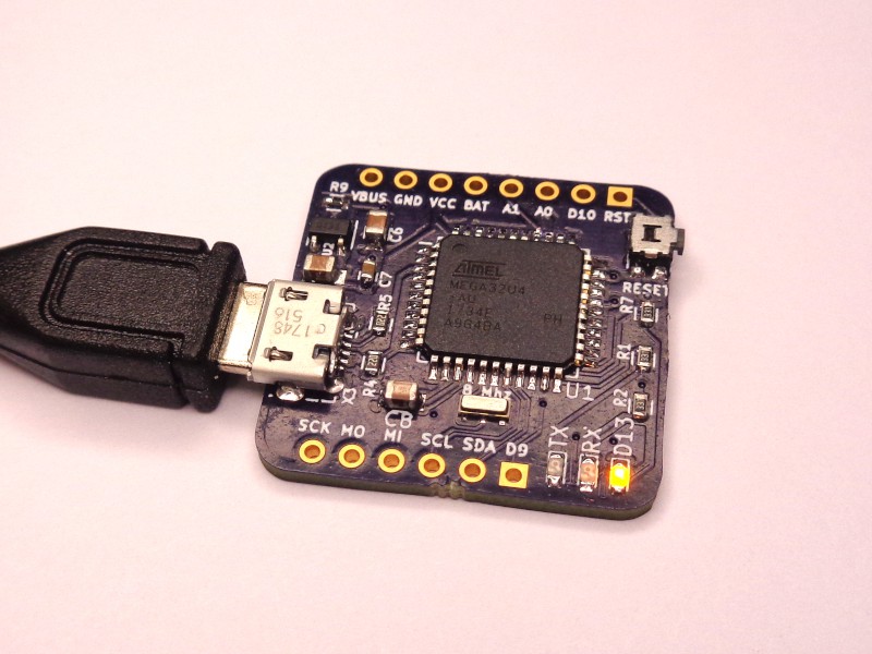
- Rev 0.0 works (see photo) with no bodge wire! The only issue is the ISP marks on the silk screen were swapped. I've fixed that in the board file.
- Rev 0.1 (see rendering) moves the power diodes and polyfuse to the front to make it easier to assemble with reflow. Minor changes to chip positions. No change to header pinouts (yet).
Notes:
- Provisions for 5V operation at 16 Mhz are provided, but haven't been tested.
- I like the right-angle button idea, but not the "feels" of the actual button operation. Any suggestions?
Now, off to design the next blocks for the rocket project and see if this takes off (pun intended) . . .
Discussions
Become a Hackaday.io Member
Create an account to leave a comment. Already have an account? Log In.