Most of the logic have been tested using Arduino sketches and debugged on the serial terminal. It might have been done with a C compiler and a debugger but using real hardware allowed me use real controllers.
Next step involves timing and interrupts, as well as a connection to the MSX.
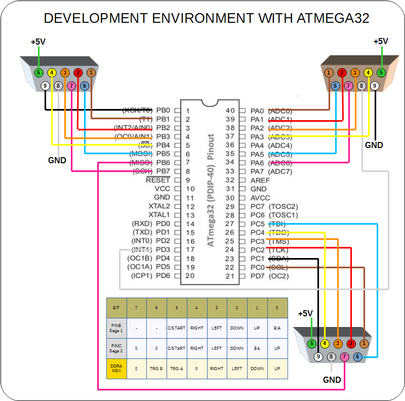
Since the circuit uses the internal oscillator and the crystal pins as I/O it is advisable to make the development using another environment: a bigger AVR (in the sense that it provides more pins). The chosen one was the ATMega32 that I have lying around on my parts bin. A rough drawing of the schematics is shown below. The output to MSX is done with PORT A leaving PORT D for loading and debugging.
A slight difference is that external interrupt 1 was used because ATMega 32 does not have pin change interrupt capability.

 danjovic
Discussions
Become a Hackaday.io Member
Create an account to leave a comment. Already have an account? Log In.