I'm shipping out the GB kits, and I thought I should PROBABLY upload the instructions for assembly. I've got a video (currently rendering) for the board, but the receiver was simple enough that I decided to do it with pictures.
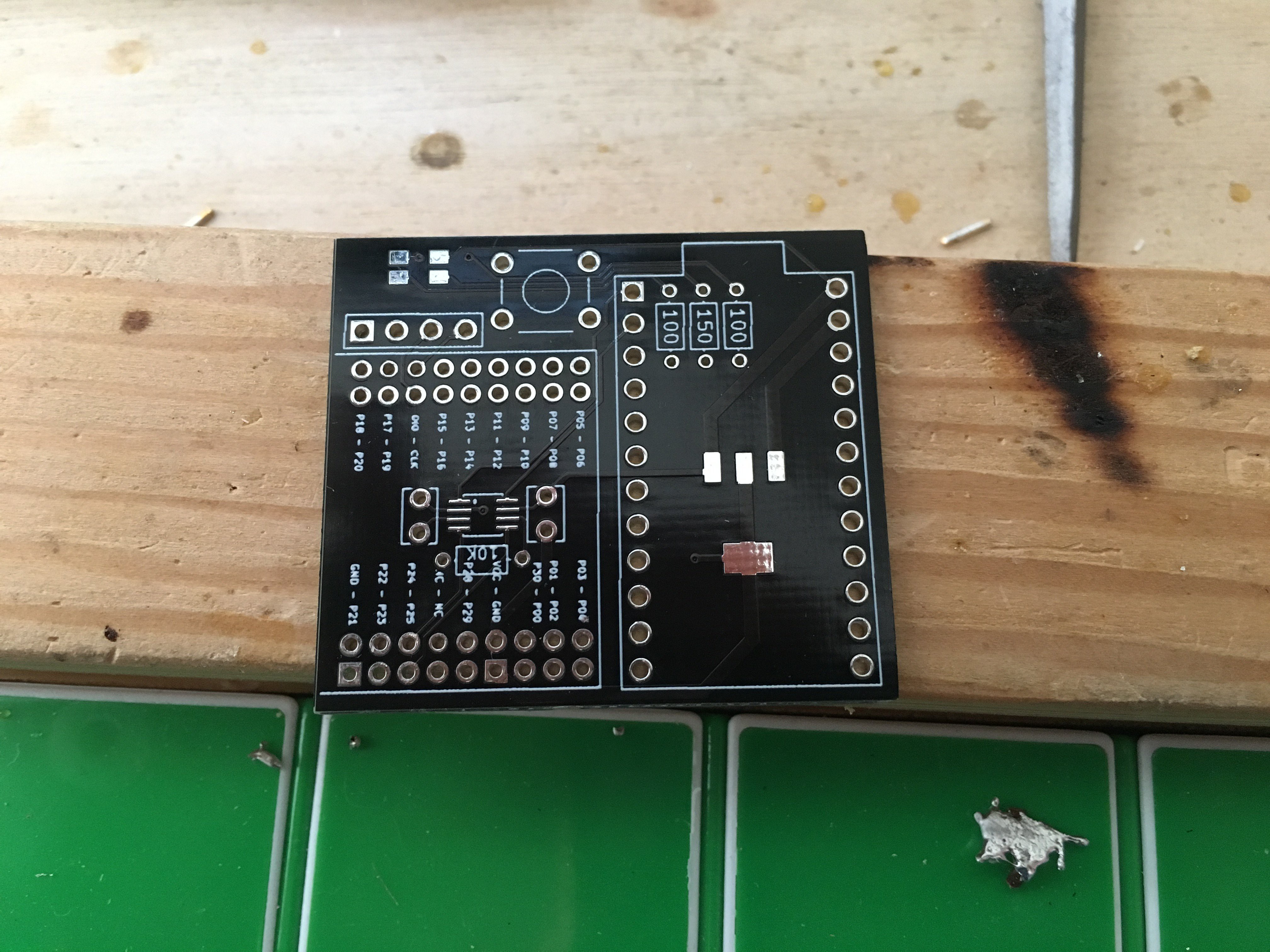
Note: The receiver PCB pictured is an older version, but it's VERY similar to the one I shipped. The main differences are: (1) on the 8-pin package (the very first thing soldered), the pictured version has a single dot to indicate orientation. The new version of the board, which shipped, has a line across the top (like the IC does). (2) The LED orientation was slightly wrong (I was using an old footprint on this one). For the PCBs that were shipped, there is a small triangle on the silkscreen of the PCB by the LED footprint. Align that triangle with the triangle mark on the top of the LED.
Let's go!
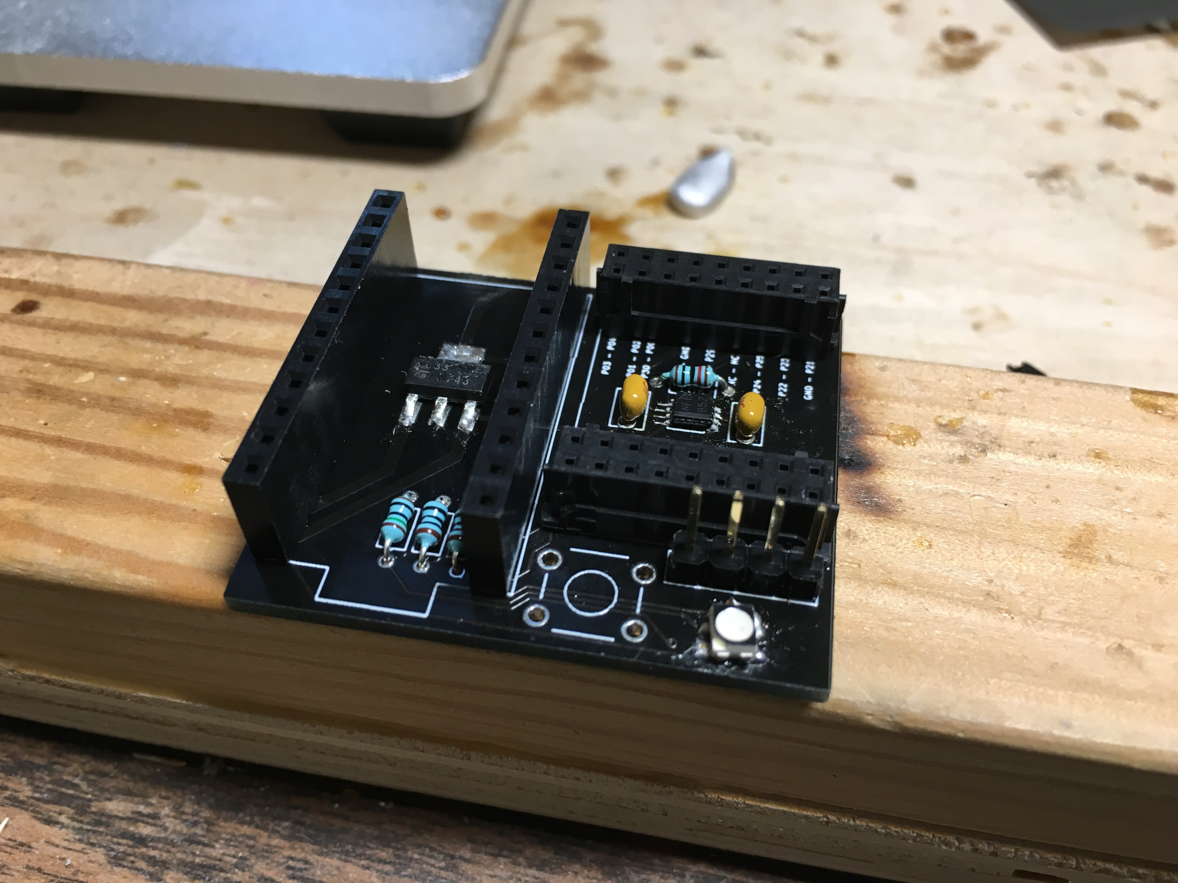
This first picture is the bare receiver board. Please note the changes between the version pictured and the version that actually shipped. We'll be soldering on the 8-pin package near the center-ish of the board. It's got a white stripe along the top that will help you identify how to orient it (hint: match it with the white line on your PCB).
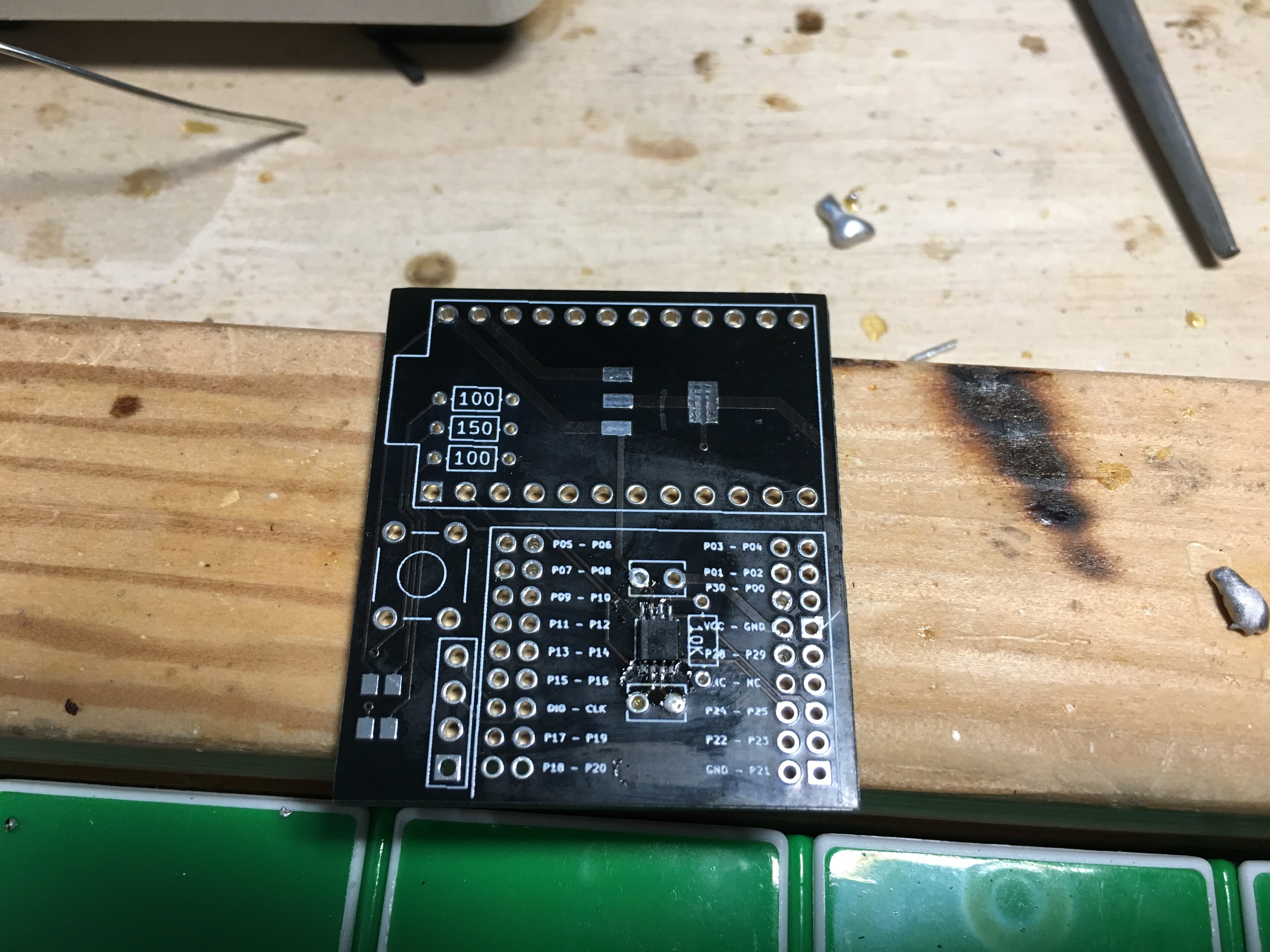
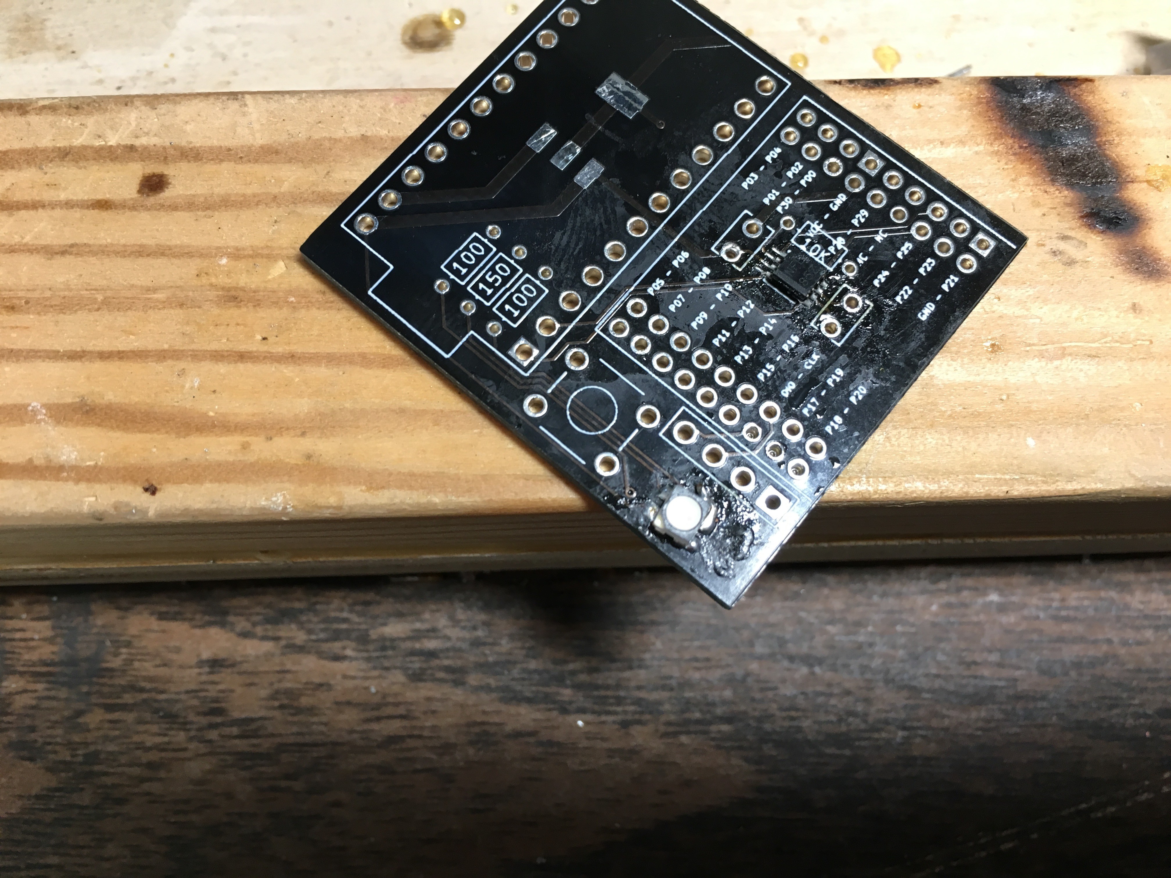
Great! Assuming you did it right. If you didn't do it right, not great. Next we'll get on the linear regulator - there's only one place/orientation it could possibly go:
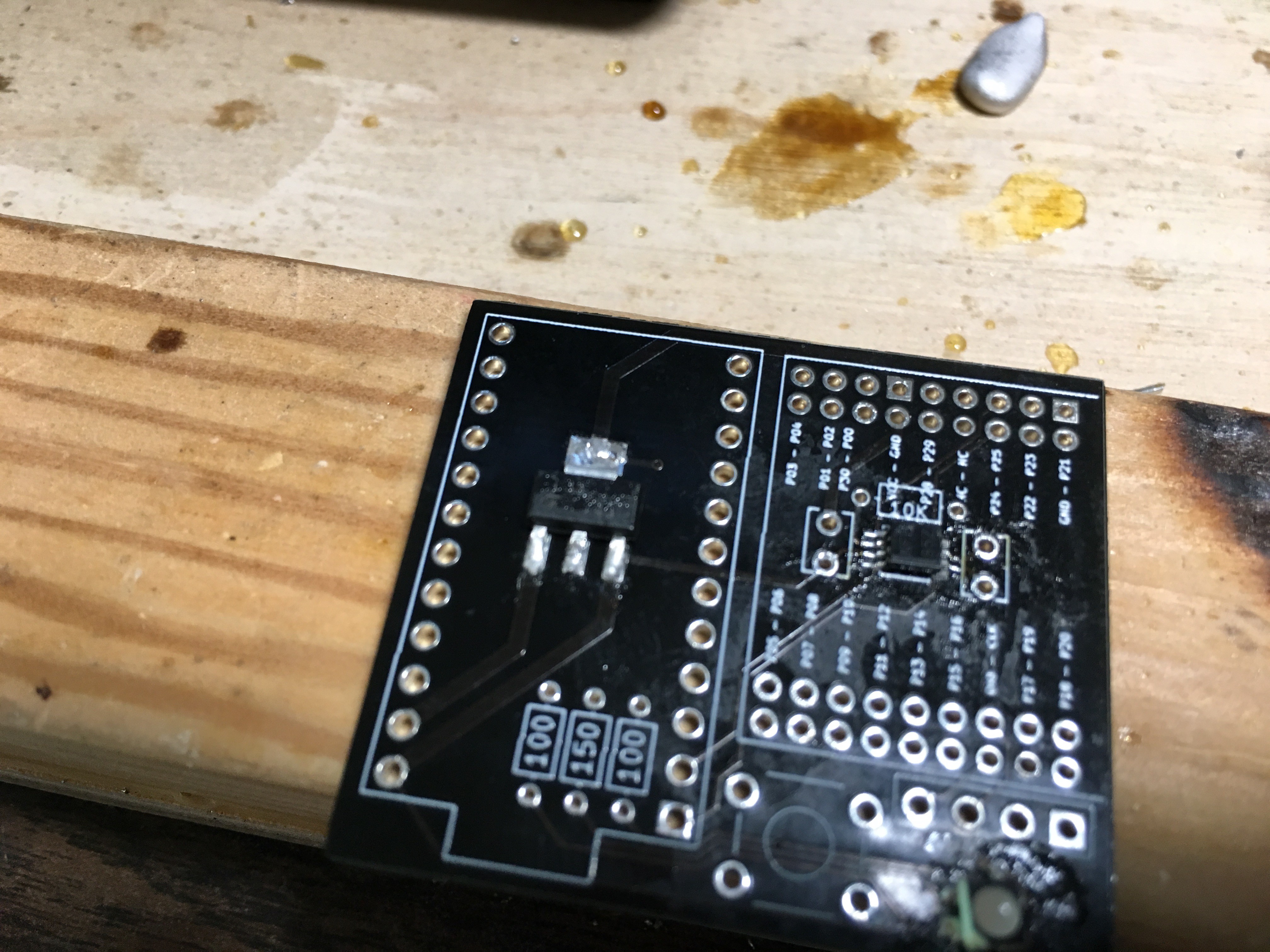
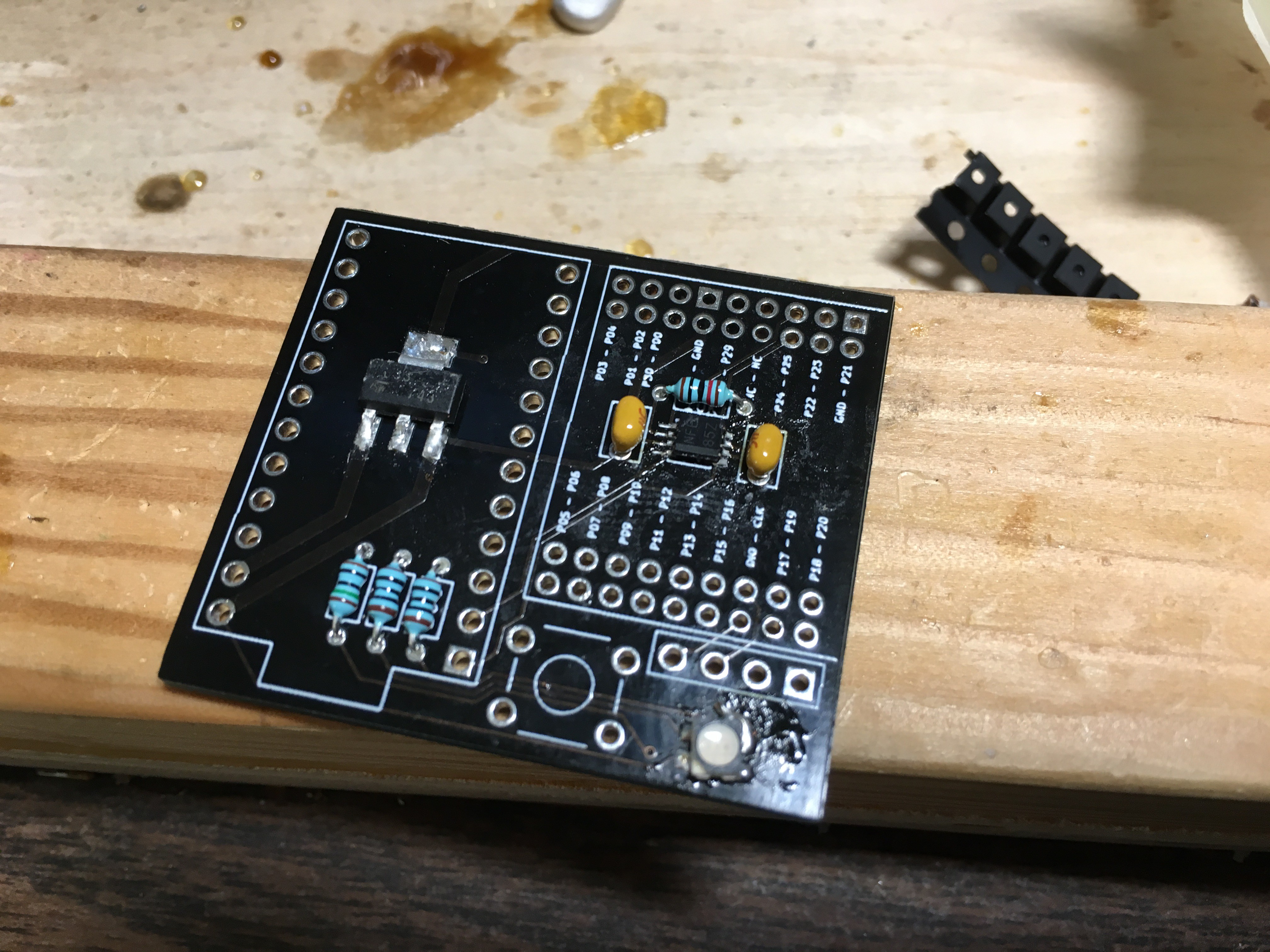
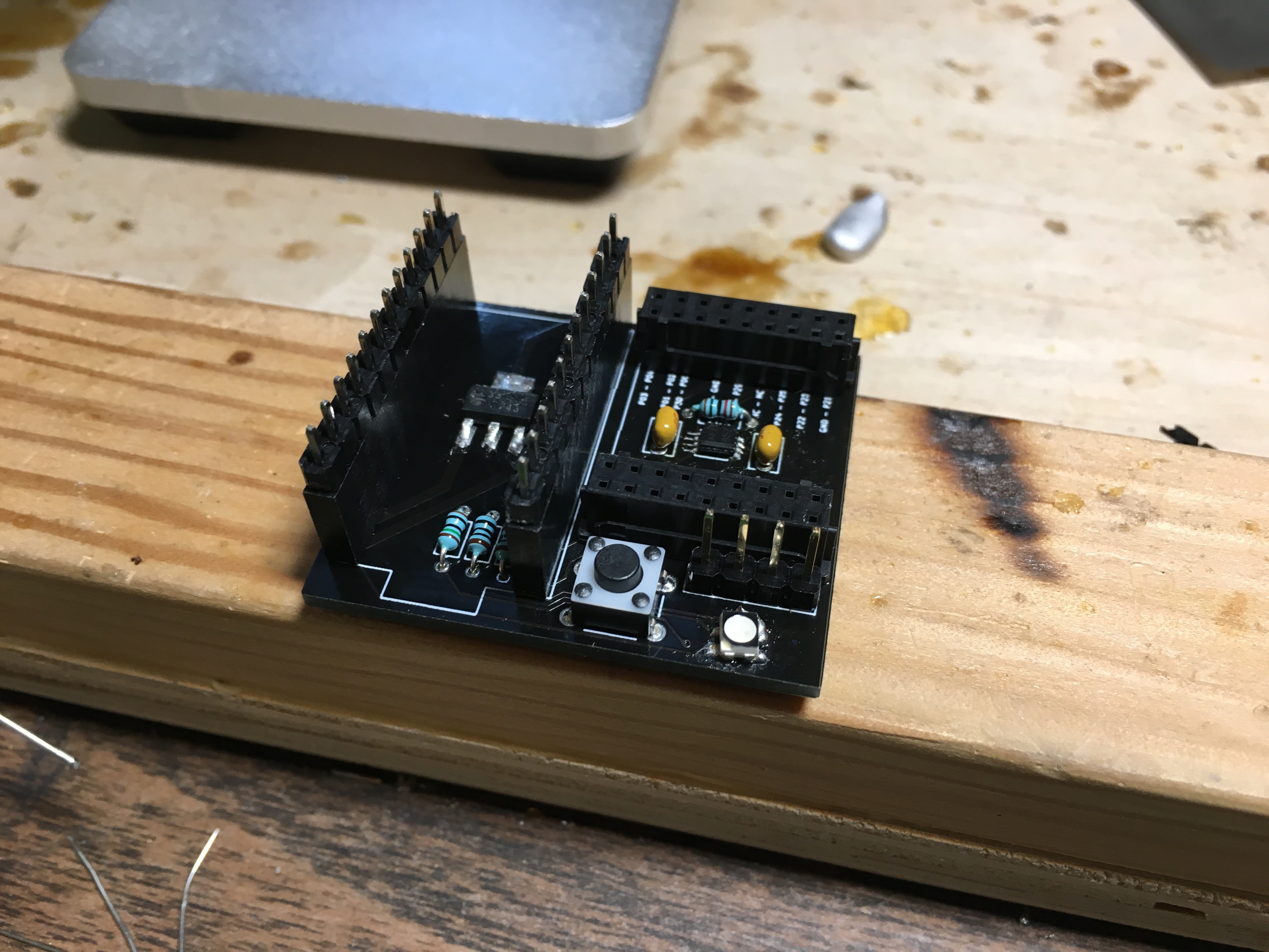
Perfect. Now the 4-pin header:
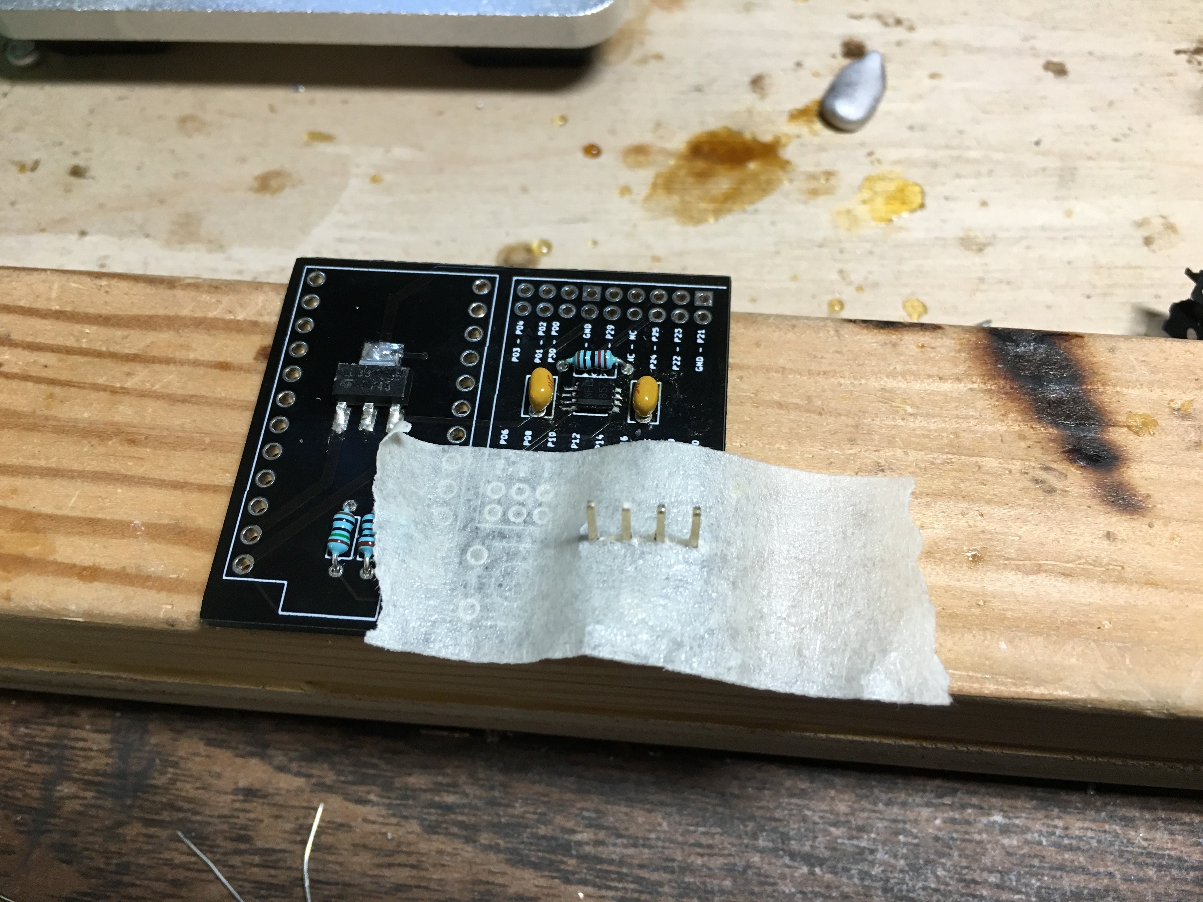
Aaaand the two 18-pin headers for the NRF:
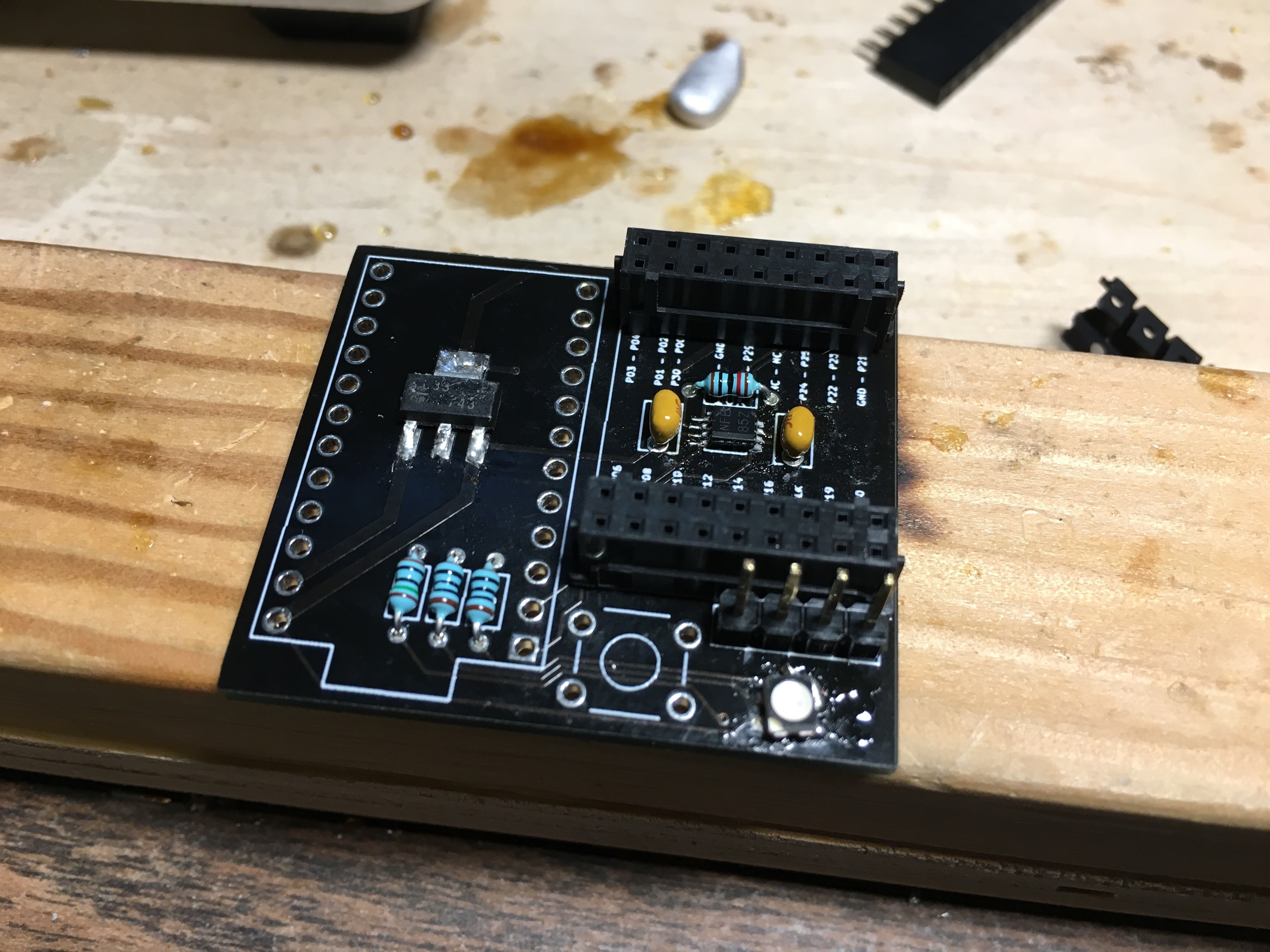
The two 12-pin headers for the Pro Micro:
And the tactile switch:
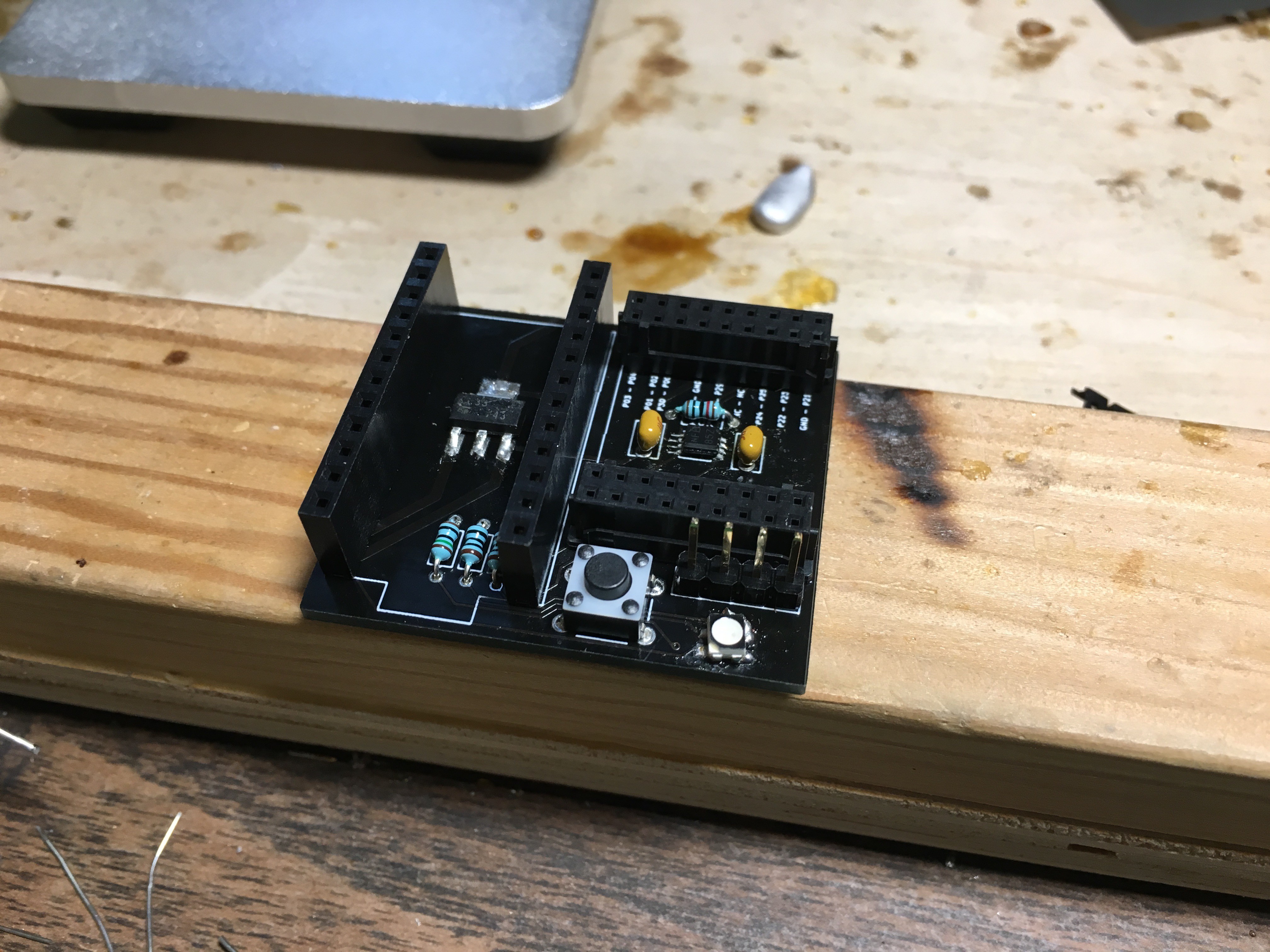
If your pro micro isn't already inserted, I recommend inserting it into the headers to solder it, to ensure it's got the right alignment.
Insert everything, and you're all done!
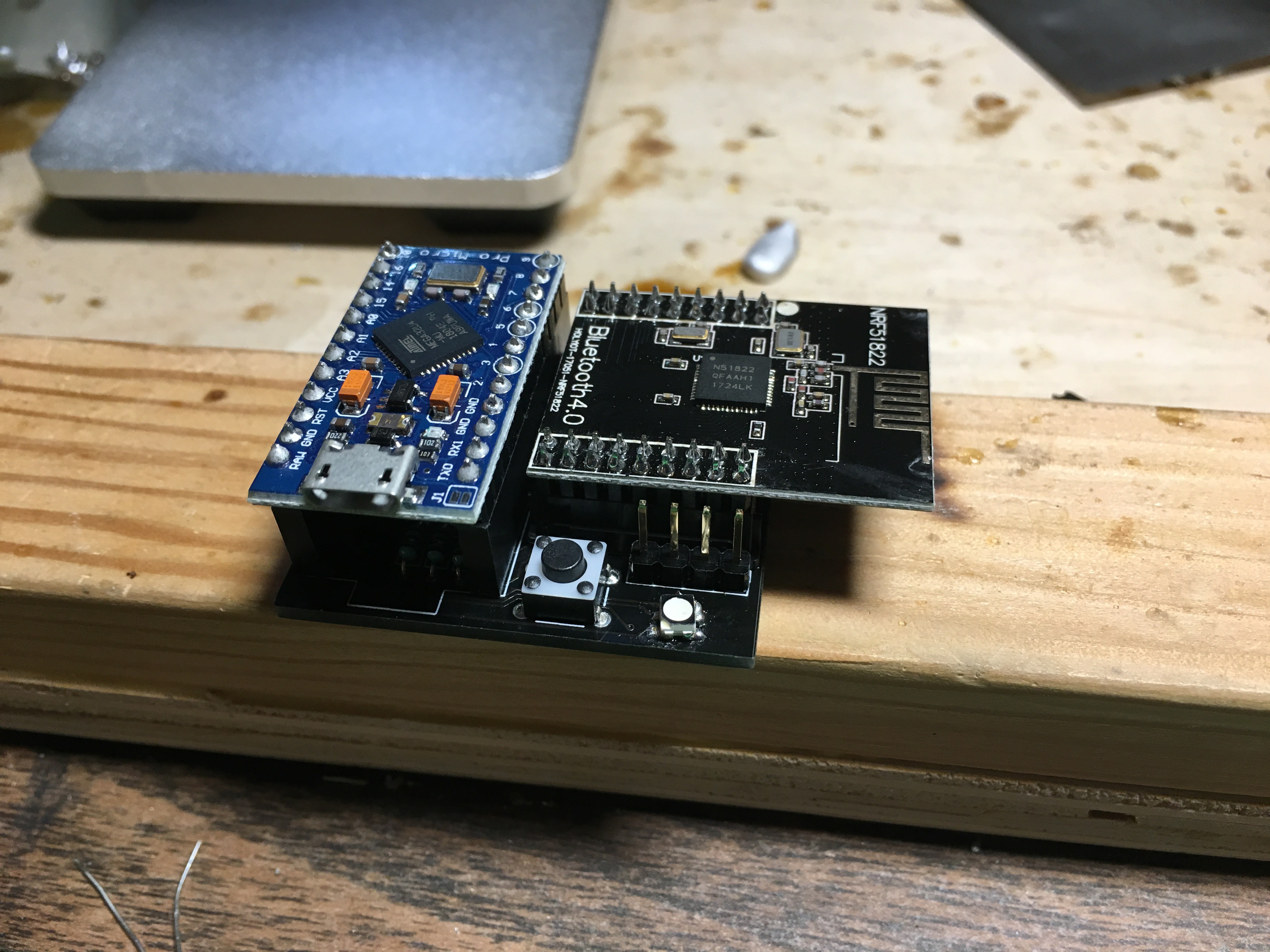
Yay, being all done. Video for the board assembly coming soon!
 Joshua Broekhuijsen
Discussions
Become a Hackaday.io Member
Create an account to leave a comment. Already have an account? Log In.