I've had a few people struggle with the receiver, so I wanted to write a guide to clarify how it works and how to test it.
The NRF on the receiver is constantly waiting to receive packets from the 2 transmitters on the Dichotomy boards. When it gets a packet, it updates it's internal memory (storing the matrix info, mouse movement, etc), and continues waiting. As often as it's able, the arduino (running QMK) requests that info from the NRF, which is sends over UART.
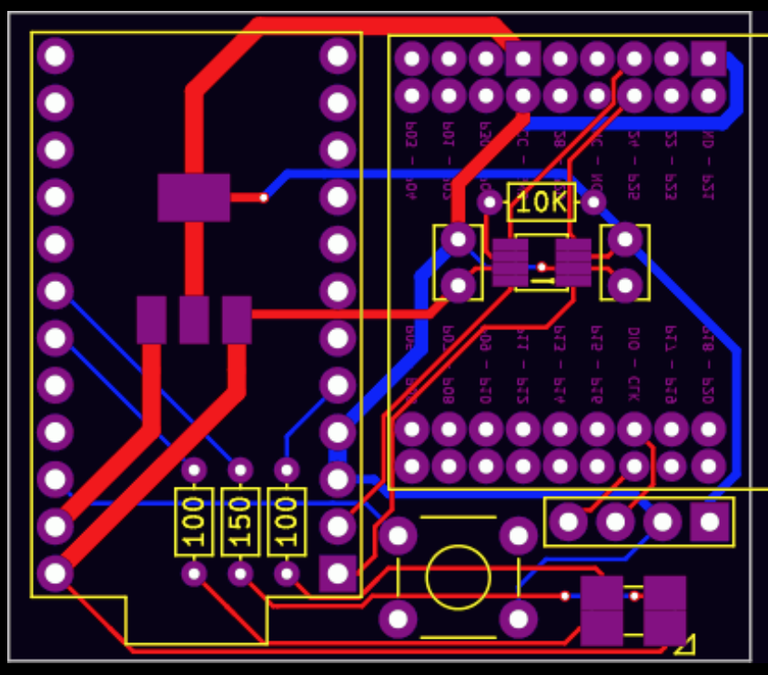
Because the arduino is at 5v and the NRF is at 3.3, there is a level shifter chip in between so nothing gets fried. This is the small, difficult-to-solder 8-pin IC underneath the NRF. Most of the time when there's an issue with the receiver, it can be traced to this.
That said, try the below steps to debug things:
1) Ensure all solder joints are good (none of the 8 pins on the small IC should have continuity with each other when everything is off/unpowered, but they SHOULD all have a continuity with another part on the board. Follow the traces to see where. Here's a picture:

2) Ensure you've flashed the receiver with QMK. If you need more details on this one, I suggest going to the QMK Discord Channel.
3) Make sure your USB cable is working - some cables work for charging (powering) things, but don't have the necessary data lines to actually facilitate communication. If your cable works for another keyboard, it should work for this.
4) If QMK is running, try using the hid_listen tool available here:
https://www.pjrc.com/teensy/hid_listen.html
If the arduino and NRF are having trouble communicating, you should get a lot of "Time out in keyboard" messages. If you don't see that, either (1) your arduino isn't running QMK, or (2), the NRF and arduino are communicating fine, but the NRF isn't receiving any packets from the transmitters.
5) Loopback test:
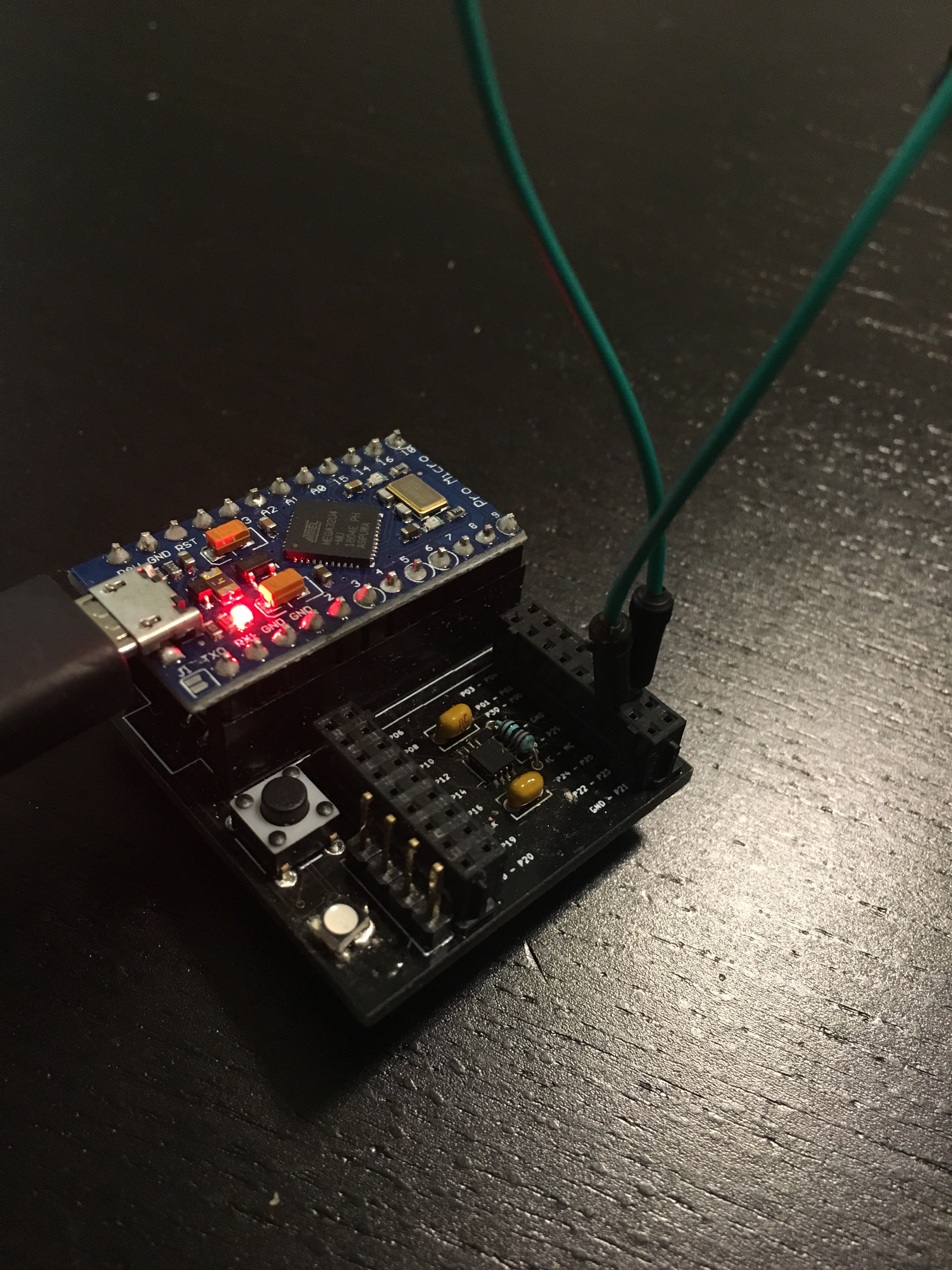
If you're seeing a lot of "time out in keyboard" in the previous step, we need to see if the 8-pin IC is soldered correctly or not. We can do this by looping any data we send back through. First, remove the NRF and insert a jumper into your receiver like so:

In case the picture is hard to make out, that's the 3rd-from-last hole in each of those rows, and that is 1 jumper, so we're bridging those two ports. Also ignore the LED, it's oriented incorrectly in this picture (this was an old version of the board, but most of it's still the same).
Once that's inserted, upload the following arduino sketch (I used the arduino IDE and the "Leonardo" board definition - I had to press the reset button twice before uploading):
void setup() {
  Serial.begin(9600);
  Serial1.begin(1000000);
  //Serial.write((uint8_t)(F_CPU>>8));
  //int received;
  //int sent;
}

void loop() {
  while (!(Serial.available())){
    //wait.
  }
  int received = Serial.read();
  uint8_t uart_data = 0;
  Serial1.write(received);
  uint32_t timeout = 0;
  while (!(Serial1.available())){
    timeout++;
    if (timeout > 10000){
      Serial.write("\r\nTime out in keyboard.");
      break;
    }
  }
  if (Serial1.available()){
    uart_data = Serial1.read();
  }
  Serial.write("\r\n UART is ");
  Serial.write(uart_data);
  Serial.write("\r\n");
}
Once it's running, open up the serial monitor and try sending anything. I sent "test," and got back this:
 UART is t

 UART is e

 UART is s

 UART is t
If that works, then your IC is soldered correctly, and the problem is apparently the NRF. It's either fried, or running the wrong program. A guide to reprogram the NRF will be up soon.
If instead, you get something back like:
Time out in keyboard.
 UART is

Time out in keyboard.
 UART is

Time out in keyboard.
 UART is

Time out in keyboard.
 UART is
Then it's likely that your 8-pin IC (bi-directional level-shifter) is either (1) fried, or (2) not soldered properly, or (3) both of the above.
Hopefully this was helpful - let me know if you have any questions, the discord (invitation/link sent out in the last Group Buy update email) is a great place - or comment here.
 Joshua Broekhuijsen
Discussions
Become a Hackaday.io Member
Create an account to leave a comment. Already have an account? Log In.