 Leonardo Gomes
The hardware for measuring the touch sensor and for communicating with the computer and the stimulation interface of the TouchYou needed to meet some requirements, for example being portable and having wireless communication. For reading the touch sensor, I used a breakout board with the MPR121 capacitive touch sensor controller. This module features twelve electrodes detection, configurable I2C address, a filtering system with debounce, and proximity detection and auto-calibration. The interface with the touch controller was made by using an Arduino Pro Mini board, with was connected with a HM10 Bluetooth module for the wireless communication. We also included a 3.7V Lipo Battery and a USB Lipo charger module, for hardware portability. A button for selecting the function mode, a LED and a vibration motor were also included for visual and tactile response for the hardware functioning.
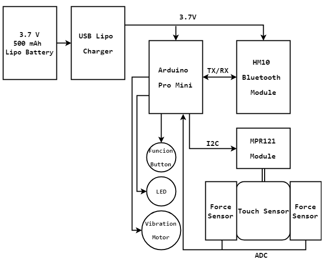
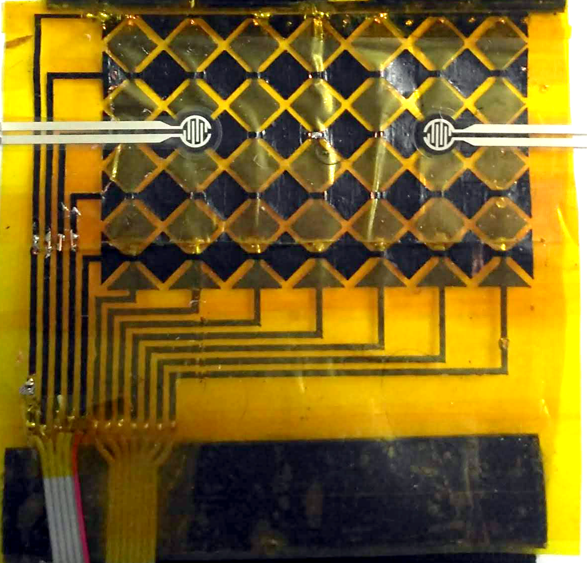
In addition of measuring the position where the touch occurred, we also measure the pressure (or the force) of the touch. For the pressure sensing function, we chosen to use two force-sensitive resistors (FSR) attached to the surface underneath the touch sensor.
Discussions
Become a Hackaday.io Member
Create an account to leave a comment. Already have an account? Log In.