Close
0%
0%

Blink An LED Entry: BlinkIR

My entry for the Mouser and MacroFAB Blink An LED competition. Blinking modules that interact with each other.

Similar projects worth following
This is my entry to the Mouser and MacroFAB 'Blink An LED' competition. The design brief is to design a project that can blink a LED or multiple LED's.More info on the competition can be found here:https://macrofab.com/blog/macrofab-design-contest-blink-an-led-sponsored-by-mouser-electronics/

My Idea is to try to make a individual pieces that blink but also interact with each other. 

Each piece will contain:

-Battery holder ( later dropped because in impeded the boards design and function)

 -MCU (possibly a ATTiny10)

-IR Photo-transistor

-IR Diode

Each piece will not only blink interdependently but also be triggered by a signal sent via the an IR connection to generate organic patterns. The design is to be able to be sewn onto fabrics and clothing to great a tapestry if blinking lights.

The units are triangular so they can be faced up against one another, with sew-able connection tabs in each corner so Power and Ground can be provided to each unit.
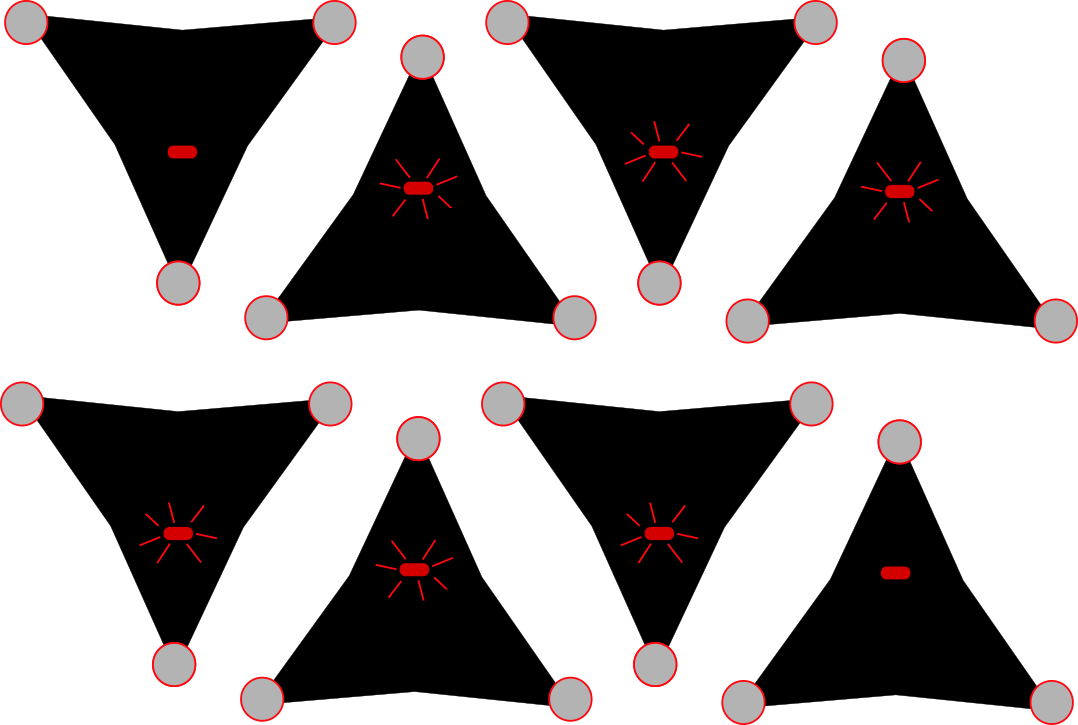
Each unit is capable of a random delayed blink sequence but when the units are placed together one unit will trigger the other 3 units adjacent to it. and they in turn will trigger other units going outwards.

The theory is that together they will make a ripple pattern of blinking LEDs similar to ripples on a pond. 

All the project files can be found at https://github.com/rabid-inventor/Blink-An-LED-Entry-BlinkIR , as well as the current version upload here.
Blink-An-LED-Entry-BlinkIR.zip

Full project Including current version of the firmware artwork used, Kicad design files and Gerbers.

x-zip-compressed - 975.80 kB - 09/09/2018 at 21:21

Download

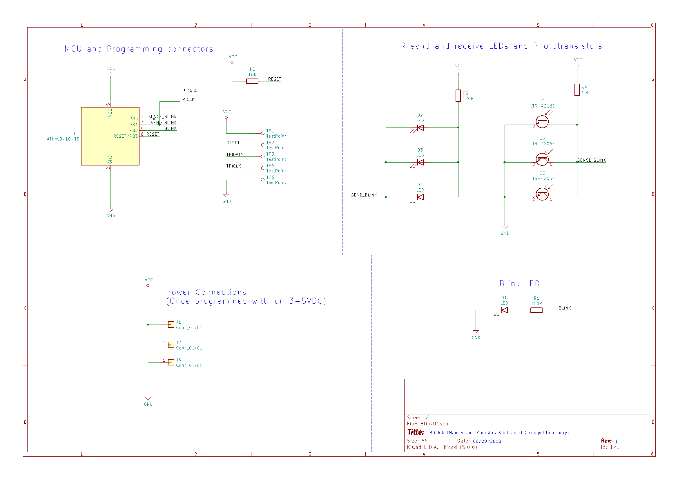
SchmaticProductionREV1.pdf

Schematic for final REV1 design

Adobe Portable Document Format - 53.18 kB - 09/08/2018 at 22:24

Preview

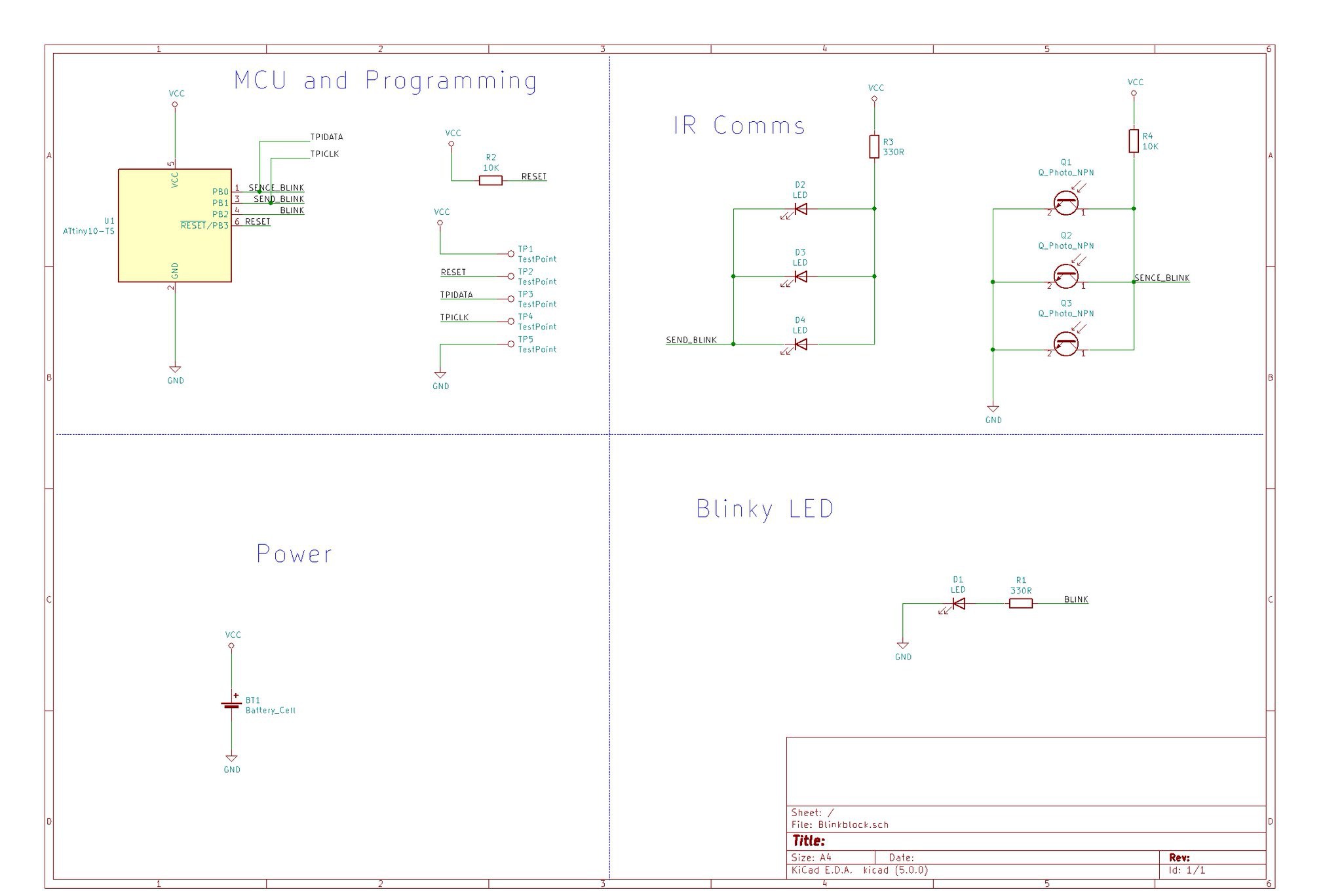
BinlkIRSchmV1.jpg

BinkIR REV1 schematic (now deprecated please refer to SchematicProductionREV1.pdf)

JPEG Image - 288.64 kB - 08/29/2018 at 10:34

Preview

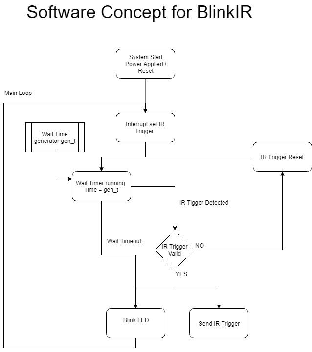
BlinkIRSoftwConcept.jpg

Concept for software.

JPEG Image - 39.38 kB - 08/29/2018 at 10:28

Preview

View all 9 components

  • Making them up.

    Gee Bartlett09/15/2018 at 21:25 0 comments


    Even though the competition has ended I want to finish this project it has been a bit of a whirlwind to get everything in place on time.

    So what has happened since the last post of the boards arriving:

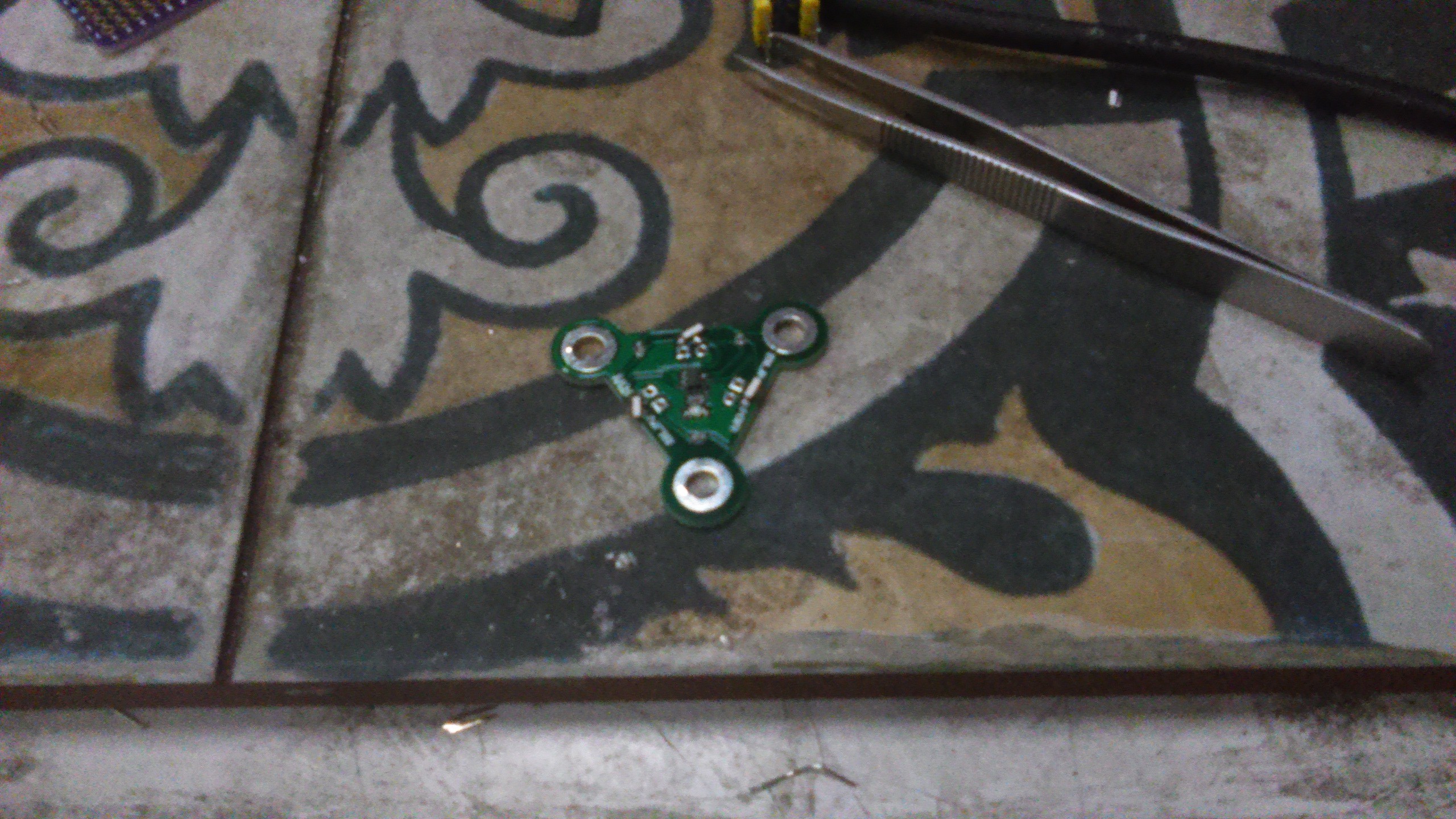
    - Made an initial unit up on Monday 10th September. The outcome was amazing I managed to program the onboard ATTiny10 via the programming testpoints I had left on the bottom of the PCB.

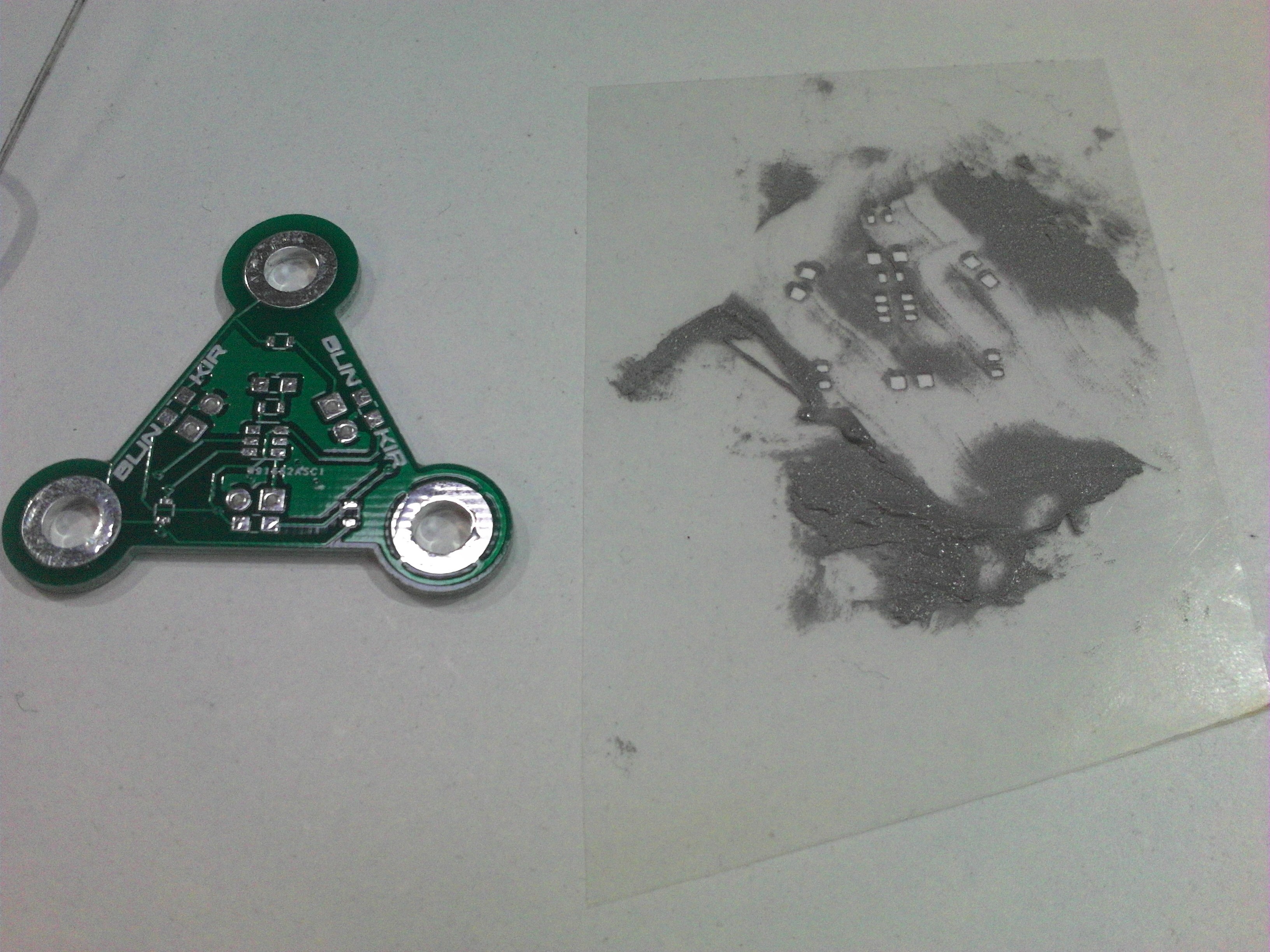
    I used a solder paste dispenser and the placed the components by hand.
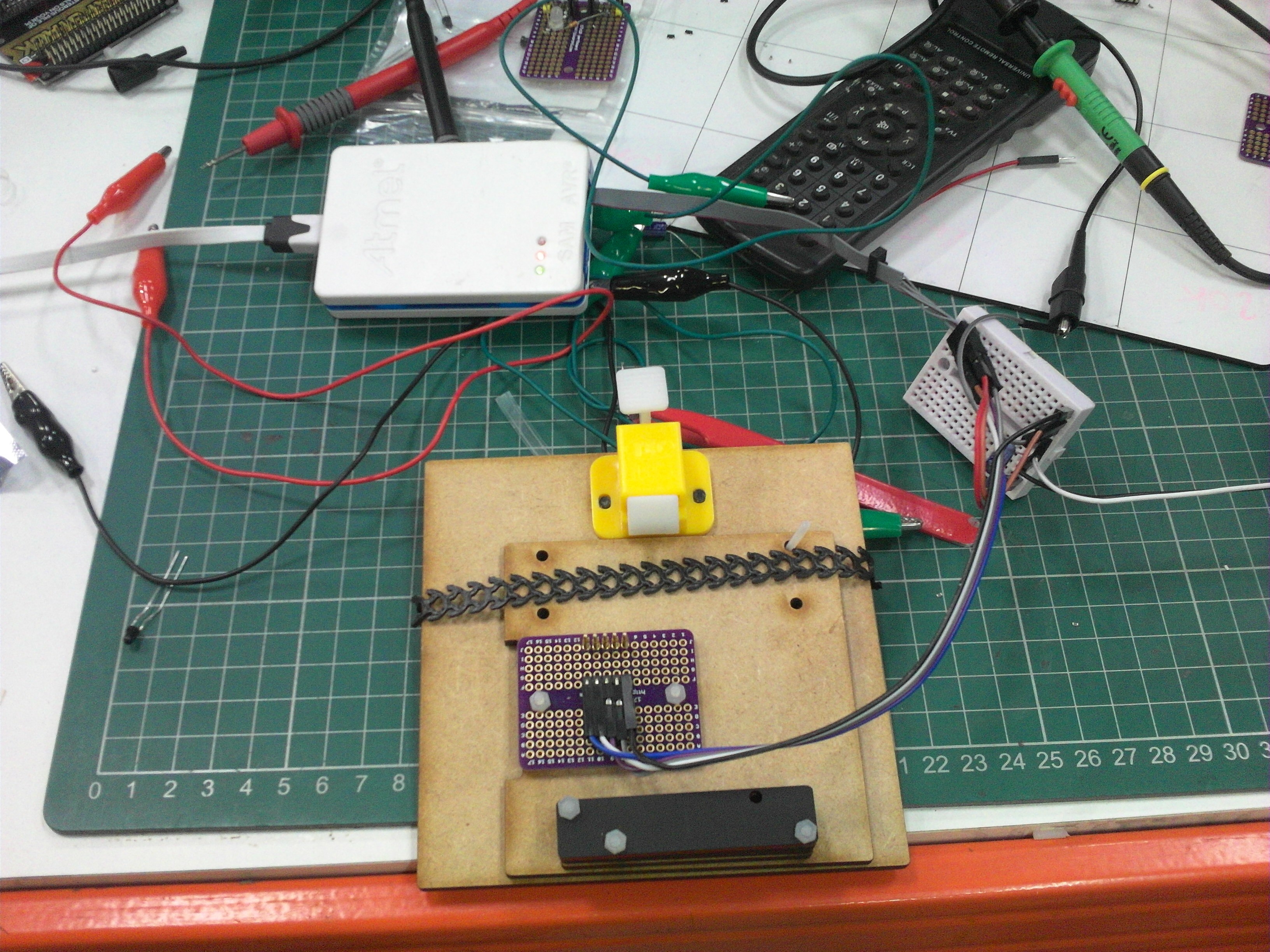
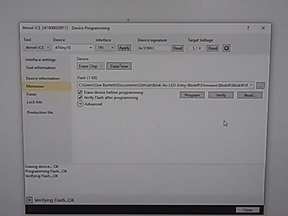
    I re-purposed a programming jig that I had used for another job and an AVR-ICE debugger to write the firmware to the badge. 

    Things to note is that the ATTiny10 will only flash at 5V+ and that not all the avr programming hardware supports the TPI interface used on the Tiny10. (for example the AVR Dragon doesn't support it).

    To my joy the blue led on the the BilnkIR started to blink as expected.

    It only needed a few firmware tweeks I had two pins the wrong way around and the IR send leds where Active LOW instead of active HIGH, so few seconds to do a bit swap and it was time to build more.

    I used a laser cutter to create Mylar stencil so I could make up 6 more units.

    I managed to get them programmed and blinking but would they blink together ?

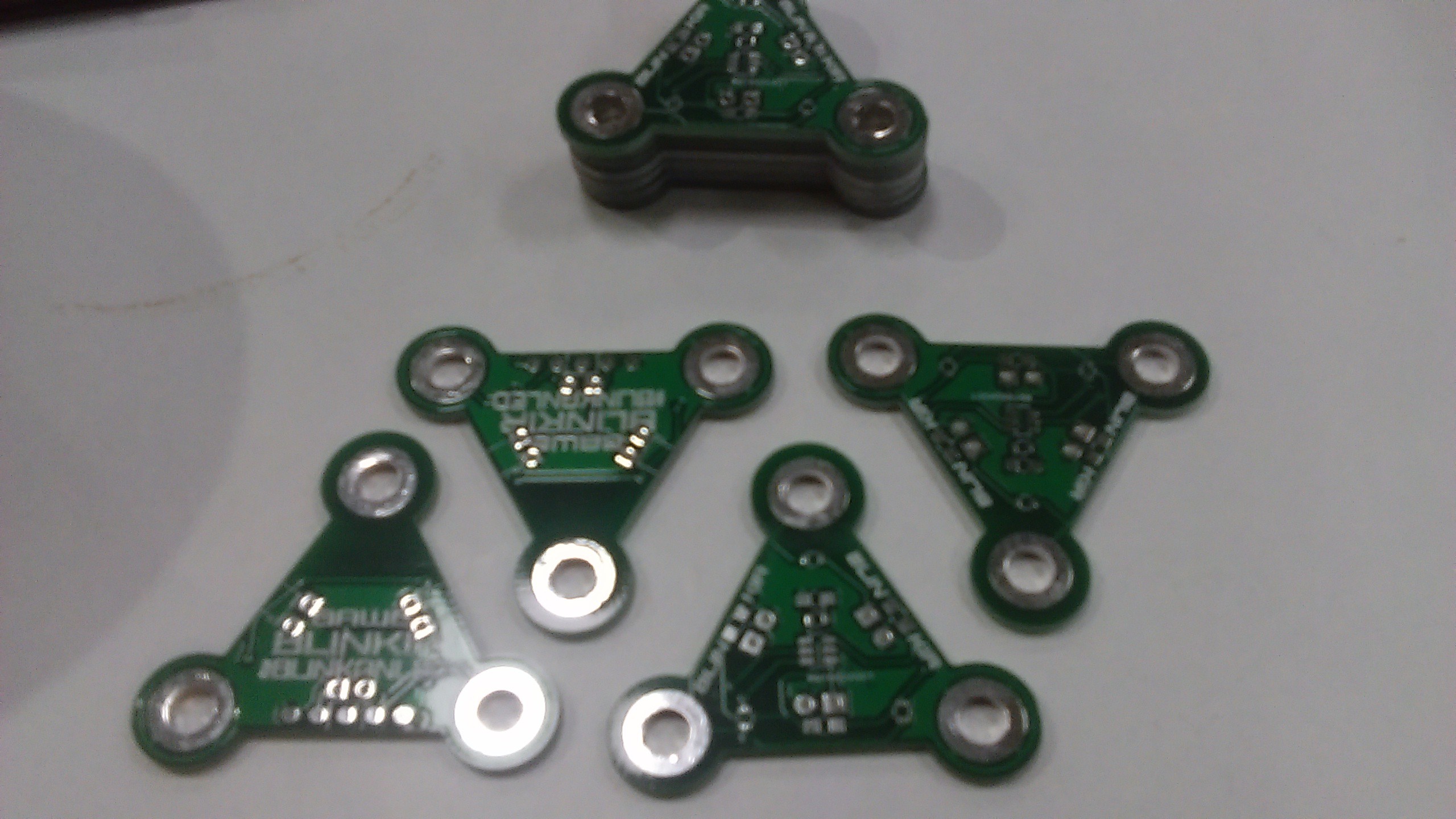
  • They Arrived Wooooo

    Gee Bartlett09/10/2018 at 14:23 0 comments

    Unfortunately after the competition dead line. :(

  • Nooooooo Boards :( , and a prototype demo

    Gee Bartlett09/10/2018 at 08:32 0 comments

    Well disappointment is in the air, I checked my shipping notifications this morning only to find this:

    Nooooo, I have unit 2pm BST which should be 8am CST. 

    oh, well time for a second bread board prototype to show how they operate together.

    The nice thing when is comes to recording is that you can see IR LEDs sorry about the shaky camera work. :D

  • Racing towards the finish. POC and function description.

    Gee Bartlett09/09/2018 at 21:43 0 comments

    At this point in the project I am facing towards the finish. Finally have some functional firmware written ( a little rushed i have to add ). I am now waiting on the PCB's showing up hopefully tomorrow morning keeping my fingers tightly crossed.

    I have done a video to describe the functionally of the project I hope you enjoy.  

    Thanks For Watching

  • Scale check and production

    Gee Bartlett09/08/2018 at 23:16 0 comments

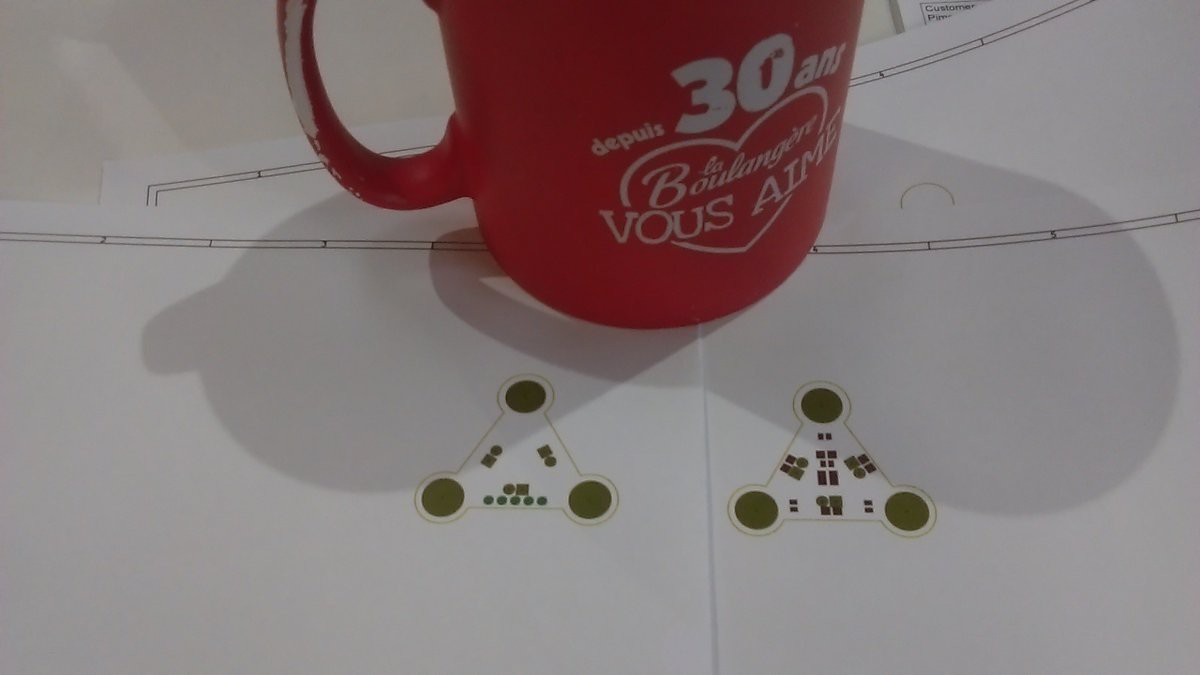
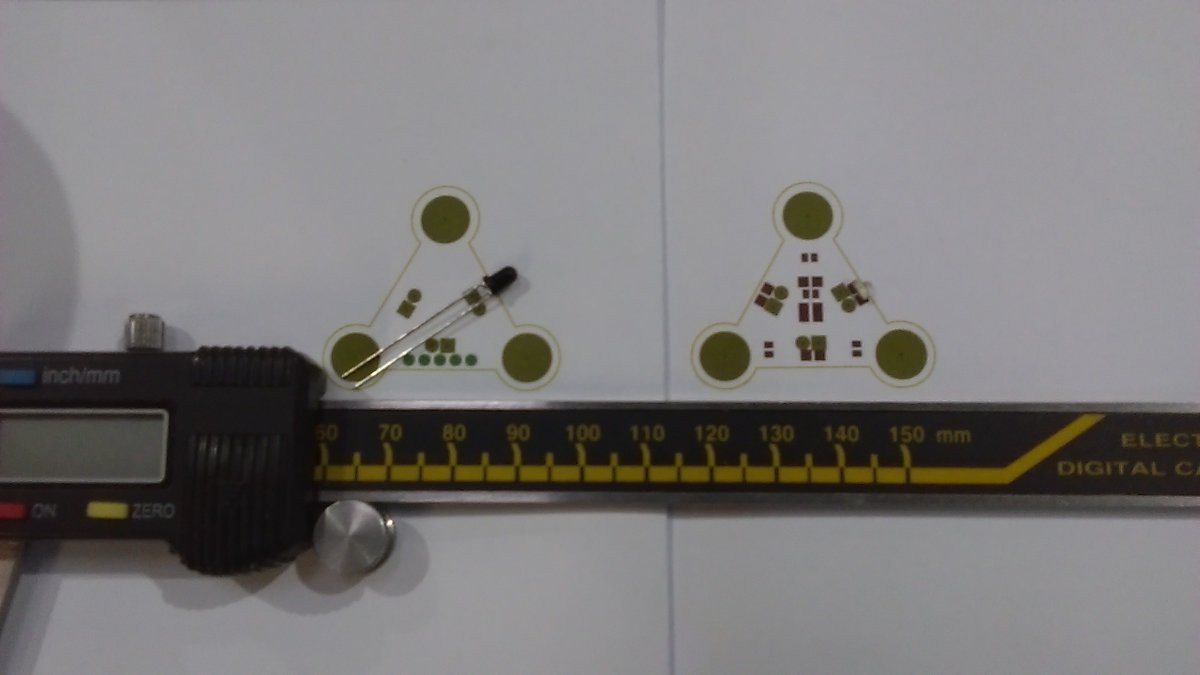
    One thing i like to do for a sanity check is to print out a pcb design 1:1 scale and lay out some of the components.

     Just allows me to make sure things are going to fit. 

    With all that checked:

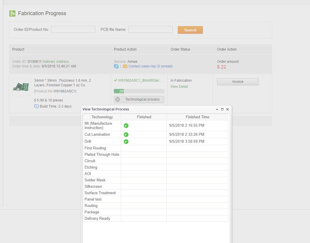
     I created Gerber files checked them over in Gerbv and then sen them off to PCBway for manufacture.

    This was on the 5th September  the competition deadline is 10th September and this is my first time using PCBway normally I use dirtyPCB. 

    I'm hoping :) in fact going to check the delivery schedule again......... 

  • From sketch to board

    Gee Bartlett09/08/2018 at 23:09 0 comments

    I want to share as much of the design process i went through to get to a finished board. 

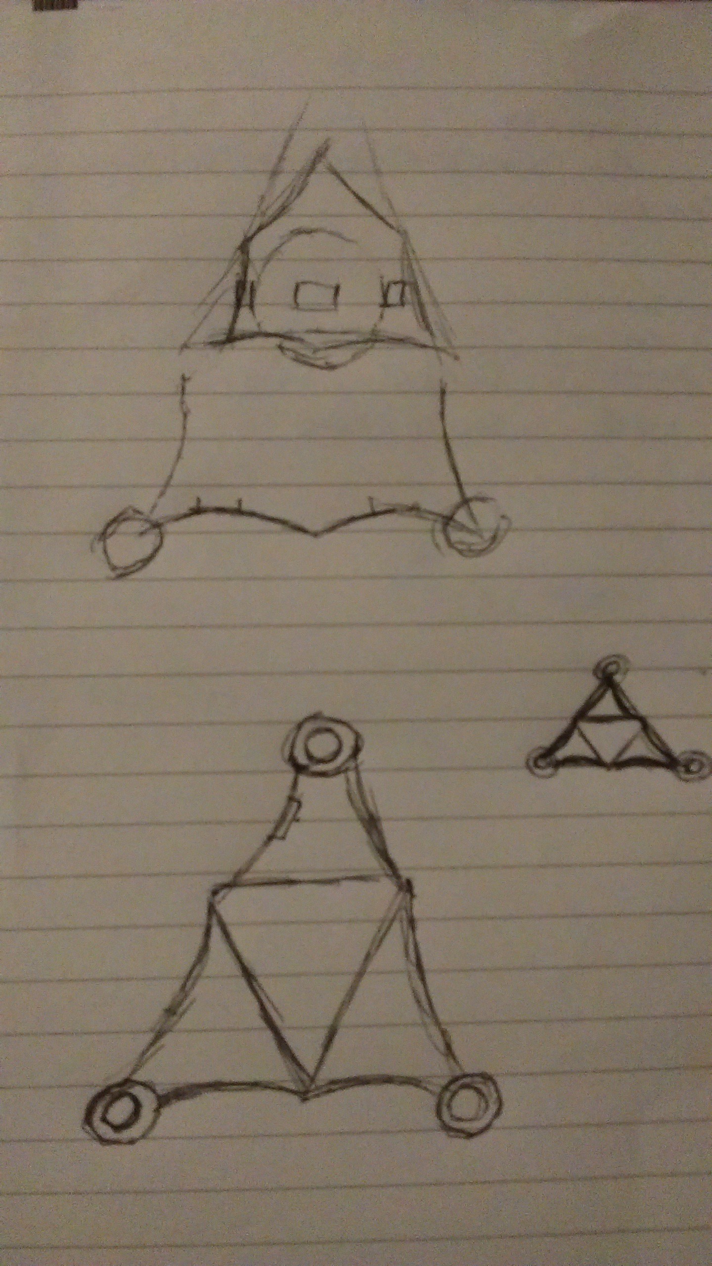
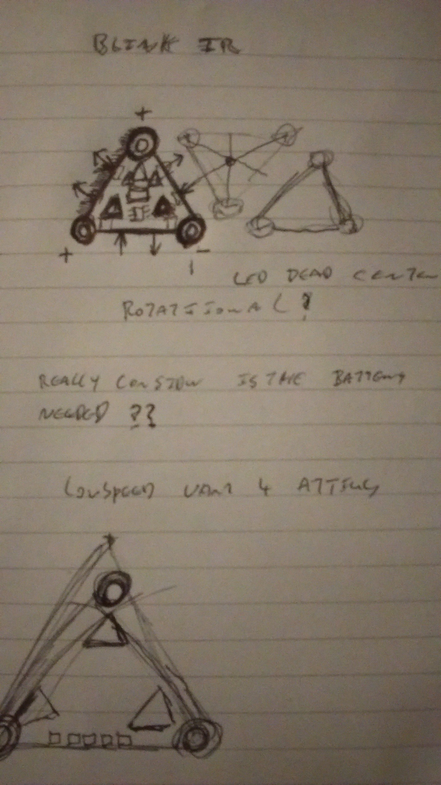
    I like to try and get stuff down onto paper really early on in the design process, for me it is important to get a good feel of what i want to achieve and sometimes it is even handy to go back to when feature creep come wandering in.

     Having an overall triangular shape was important, It would help to make interesting shapes and patterns when the units are placed close to each other. Also note the rings on each corner for the sew-able connections . Also to note is my early attempts to fit a CR2032 coin cell holder as much i looked the battery dominated the rear for the PCB and left no room for the IR send and receive in the lower edge of the board, which is what lead me to eventually drop it .

    Once I got rid of the battery holder the board became far more compact and it allowed me to consider the IR LED positions and how the units would communicate with each other. 

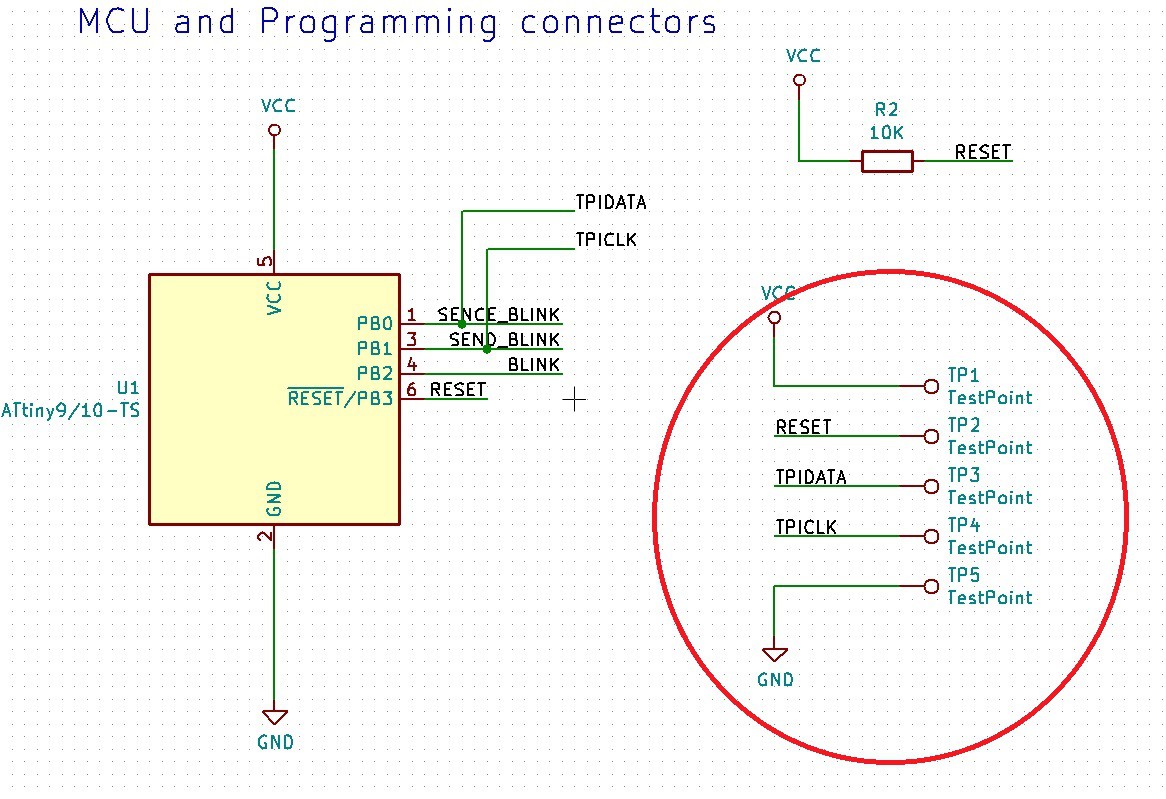
    Note in the lower image the 5 small squares at the bottom, these are underside contacts which will be used to program the on-board  MCU. 

    These can be seen on the schematic:

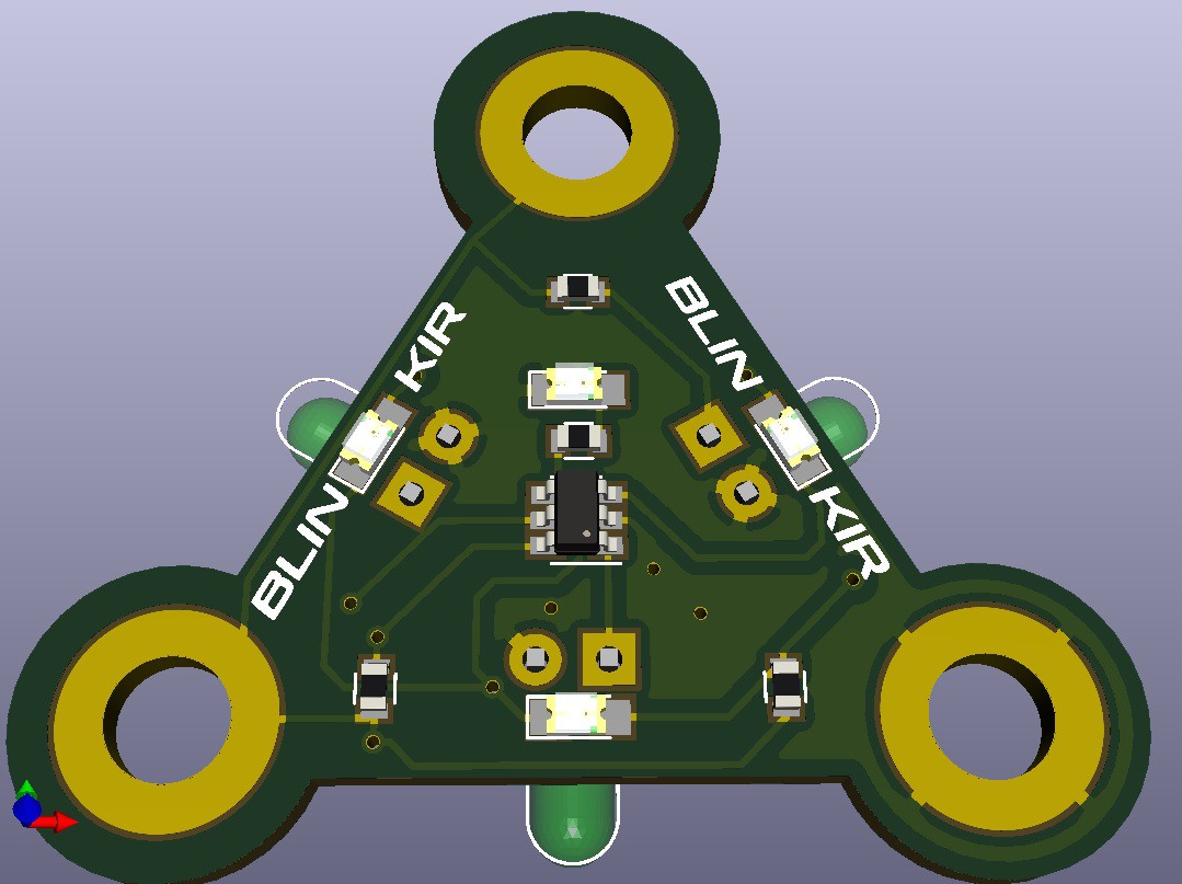
    The raced to bring the concept to life:

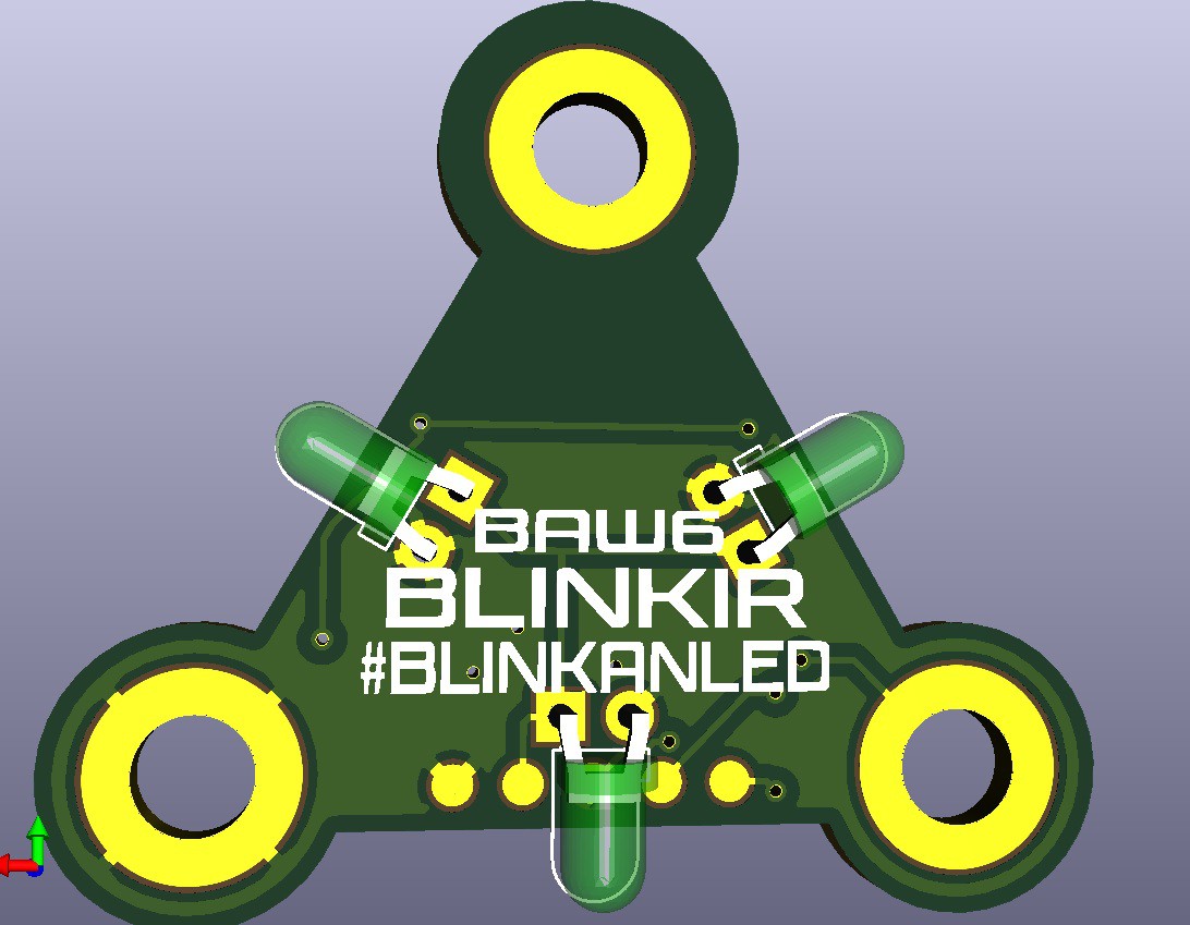
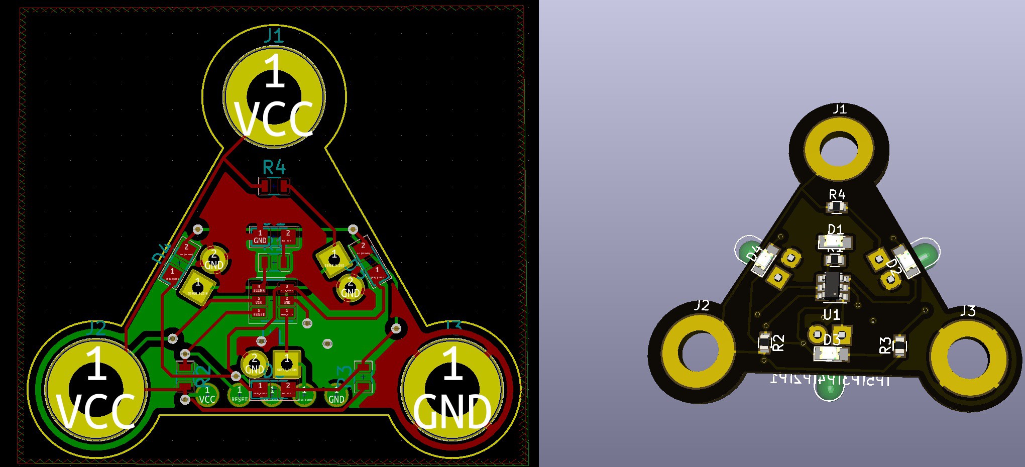
    The idea was to try to keep the design and assembly simple as possible the SMT components are on the topside with only 3 through hole placements for the photo transistors. I ended up with this because i wanted to prevent self triggering, avoid double sided SMT placement (with the battery holder it seemed pointless) and i had been testing the IR communications with through hole phototransistors.

    In my own admission the silkscreens where rushed time was running out and needed to get these boards sent for manufacture soon. Also note the programming pads on the underside they are 0.1 inch spaced pads to make a programming jig easy to assemble on some strip/perfboard.

  • Having the power

    Gee Bartlett09/08/2018 at 22:36 0 comments

    I started my initial routing from the schematic I shared before. Much to my disappointment i couldn't settle on a board outline that was beneficial to what i an wanting to achieve without making the board bigger and bigger. 

    I always wanted to have the individual units powered via sew-able tabs so after soul searching have decided to make this a wearable/soft project.

    As you can see in the bottom left of the schematic I have added the pre-mentioned sew-able tabs which will be used for main power. 

    I intend for these tabs to either be used with conductive thread of which i have some to hand, or to use tradition bus bar or single core bell wire to solder them together in interesting shapes.

  • Quick and Dirty Prototype

    Gee Bartlett09/01/2018 at 22:39 0 comments

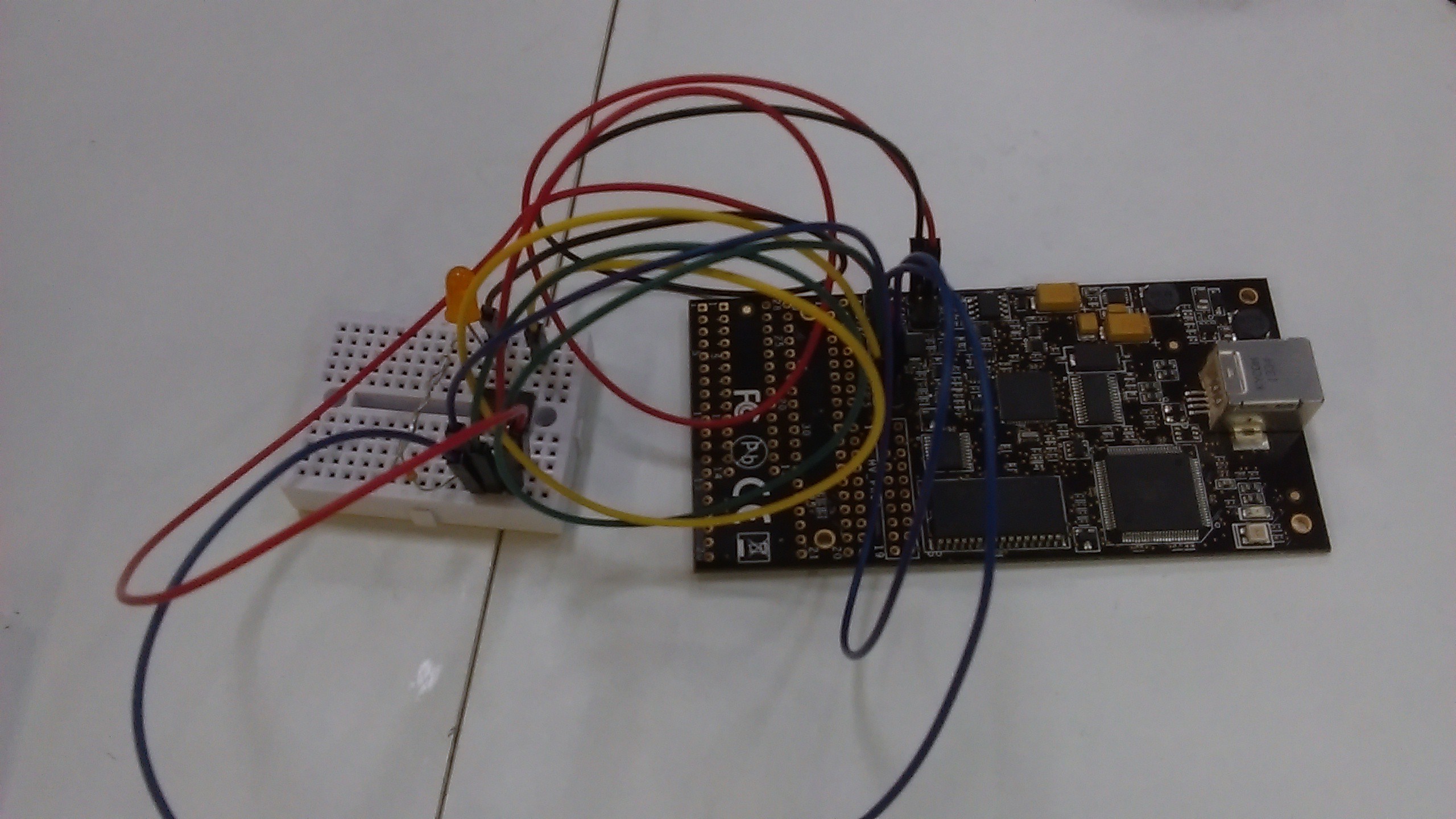
    I have decided to try and mock-up a prototype/POC I had a good search around I was certain to have some ATTiny's to prototype with and hopefully write some code that will be pin compatible with the final design.

    In the end managed to settle on some through hole ATTiny85's .

    Opened up AVR studio and raced to get it to blink. Did it:

    It blink and on PB0 which is the pin i want to use for the main LED.

    now just have to start figuring out how the states will work for sending the blink to other boards. 

  • First Schematic concept

    Gee Bartlett09/01/2018 at 22:24 0 comments

    I'm looking at using and ATTiny9 or 10 for this project to keep the board space assemblability and power overheads down as much as possible. So keeping that in mind I have done an initall schematic in Kicad.

    I have added a CR2032 battery holder and the main blink LED in the lower right side of the schematic. I have broken out the programming pins for the ATTiny and made sure there is a pull-up resistor for the reset line to avoid and funny business.

    Things I'm haven't really considered a the moment is decoupling the MCU with some 100nF and 1uF capacitors. and the sew-able connections of they are an option for providing power.

  • Thrashing out the concept

    Gee Bartlett08/29/2018 at 09:05 0 comments

    Started work on the initial idea for the blocks.

    Thrashing out how the software should work.

    I decided on using a very small MCU for the project as I need to keep the power, cost  and PCB real-estate overheads low. The idea is to use an Microchip ATTiny10. Which is small and low cost with low power overheads.

View all 10 project logs

Enjoy this project?

Share

Discussions

Similar Projects

Does this project spark your interest?

Become a member to follow this project and never miss any updates