 Liam Lacey
Since my last log I've been busy coming up with the design of the device, in regards to both the layout of controls on the panel as well as the exact control components and microcontroller to use. In this log I'll describe and explain both of these aspects.
Here is a rough 2D sketch of the desired layout of the panel, where all dark grey item are controls (or an LCD in regards to the rectangle component):
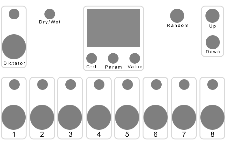
Here's a description of each section:
1 - 8
Each of these sections are for controlling each of Turnado's 8 knobs, where each contain a pair of controls - a switched rotary encoder (top) and a single-axis bi-directional thumb joystick (bottom). Both controls are used to control the same software parameter, but together they provide a more intuitive and useful method of control.
The idea is that the pair of controls work together in the following way - you use the encoder to set a 'static' value, and then you use the joystick to 'momentarily' change the value relative to the 'static' value. For example, if you use the encoder to set the parameter value to 64, you can then move the joystick up to change the value between 64 and 127, or down for values 64 to 0. To understand the reasons behind this type of control and interactivity, please see the 'Control Types and Physical Interaction' section of my last log. The push-switch of the encoder will be used as a quick way to reset the parameter value to 0.
I've decided to use a thumb joystick as the momentary bi-directional control as this appears to be the only affordable, commonly-available and compact control/component of this type. However even thumb joysticks aren't completely perfect for this design, as they are dual-axis when I only need a single axis; however I'm just going to leave the second axis disconnected and see if there is a way I can physical disable it (so that the joystick will only move in the vertical axis). These controls also usually come with a push-switch, but again I'll just leave this disconnected here. Ideally I would have liked to use miniature springed wheel lever controls, such as the pitch-bend wheels you find on most MIDI keyboards, however there doesn't seem to be any off-the-shelf versions of these and the one's I did find were too big.
I've decided to use rotary encoders rather than potentiometers, primarily so that the controller will always adjust Turnado's parameter values based on their current values. Encoders essentially just increment or decrement a value, however as potentiometers set an absolute value they could be problematic here. For example, when changing Turnado's preset the software parameter values will likely change - in this situation potentiometers would now be out-of-sync with the software and any adjustments to them will cause the parameters to jump back to the previous preset's value. A couple of other advantages of using encoders - they can include a push switch, which I'll be using for this device; and encoders allow the implementation of acceleration, where the faster you turn it the greater the value change will be. The only disadvantage of using rotary encoders compared to potentiometers is that, as they are endless (they will turn continuousness), they can't visually display the currently value of the parameter they're controlling; however one of the primary reasons of including an LCD on the device is to display these values (see 'LCD' section below for more info).
Dictator
This section is for controlling the Dictator Mode fader of Turnado in the exact same way as that of Turnado's 8 knobs (see above).
Dry/Wet
This is a non-switched rotary encoder for controlling Turnado's dry/wet mix parameter. See the '1 - 8' section above for reason behind using a rotary encoder here.
Random
This is a momentary push-button for triggering Turnado's 'random' button that creates a random preset.
Preset Up/Down
This is a pair of momentary push-buttons for changing Turnado's loaded preset.
LCD (and Ctrl/Param/Value Controls)
The LCD will be used for two main things:
- To display the current values of Turnado parameters
- To configure device settings
As none of the device's controls are able to visually display the current values of the parameters that they are controlling themselves, using an LCD seems to be the best way to do this. The LCD will display the realtime values of Turnado's 8 knobs, dictator fader, and dry/wet mix; based on either the device's control values or MIDI-in values from Turnado itself.
The LCD will also be used to configure the controller's settings, such as MIDI channel and control MIDI CC numbers. To do this it will display a menu of options that will be navigated and set using three rotary encoders:
- Ctrl - selects the control you want to configure
- Param - selects the parameter you want to set
- Value - selects the value you want to set
The Ctrl encoder will be switched to offer a quick way of viewing the menu, but the other two encoders will be non-switched.
The exact LCD I am most likely going to use is a 2.4" 320x240 TFT LCD with a ILI9341 controller chip, which can be used with a Teensy-optimised Adafruit_ILI9341 library.
Layout
I have laid out the controls as such for the following key reasons:
- Related controls are grouped together - probably the most important principle of good user interfaces design
- The 1-8 joysticks are positioned as such for the following reasons:
- They are at the front as these will be the most used controls.
- I've put them all in a single row, rather than in two rows of four like within the Turnado software interface, so that it's easier to access them all at the same time.
- The particular spacing makes it possible for you to control four joysticks simultaneously from just the four fingers of a single hand.
- The Dictator Mode controls - probably the second most accessed controls - are on the top left as I am left handed (but I'm aware this probably won't be the optimum position for most people!).
- All 'preset' related controls - preset up, preset down, and randomise - are grouped together. As they are not likely to be used as often, and their effects are a lot more dramatic (e.g. pressing 'random' will completely change the effects you'll be controlling and be irreversible from the controller) they are places as far away from the commonly accessed controls as possible.
- The LCD is positioned top-centre so that it will be less likely covered by your hand/arm as you are using the controller.
- The LCD controls are positioned under the LCD so that:
- They line up with the menu columns on the LCD that they are controlling
- You'll never need to cover the LCD with your hand/arm whilst using them (which you may do if the controls were instead on the side of the LCD).
- The layout is symmetrical.
- The exact size of the panel is based on the enclosure I am looking at using - the Takachi Electric Industrial CF27-18BB sloped enclosure.
Microcontroller
As mentioned in my last log, I want to use a Teensy microcontroller. In order to connect all needed controls without having to use multiplexers I'm going to need to use the top-of-the-range Teensy 3.6.
The above set of controls and components require the following I/O to/from the Teensy board:
- 9 analogue inputs
- 40 digital inputs
- 4 SPI pins (for the LCD)
Discussions
Become a Hackaday.io Member
Create an account to leave a comment. Already have an account? Log In.