 Liam Lacey
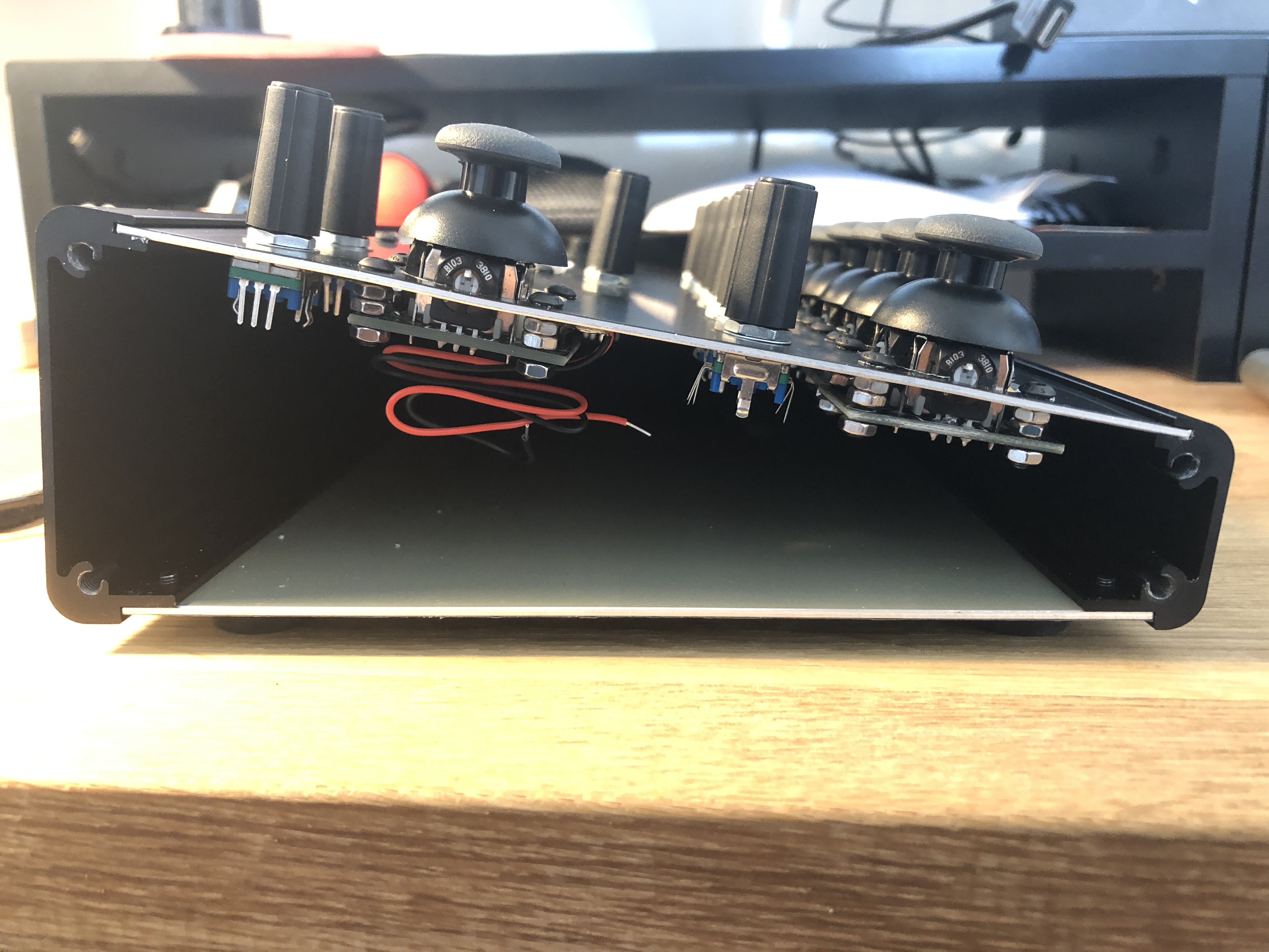
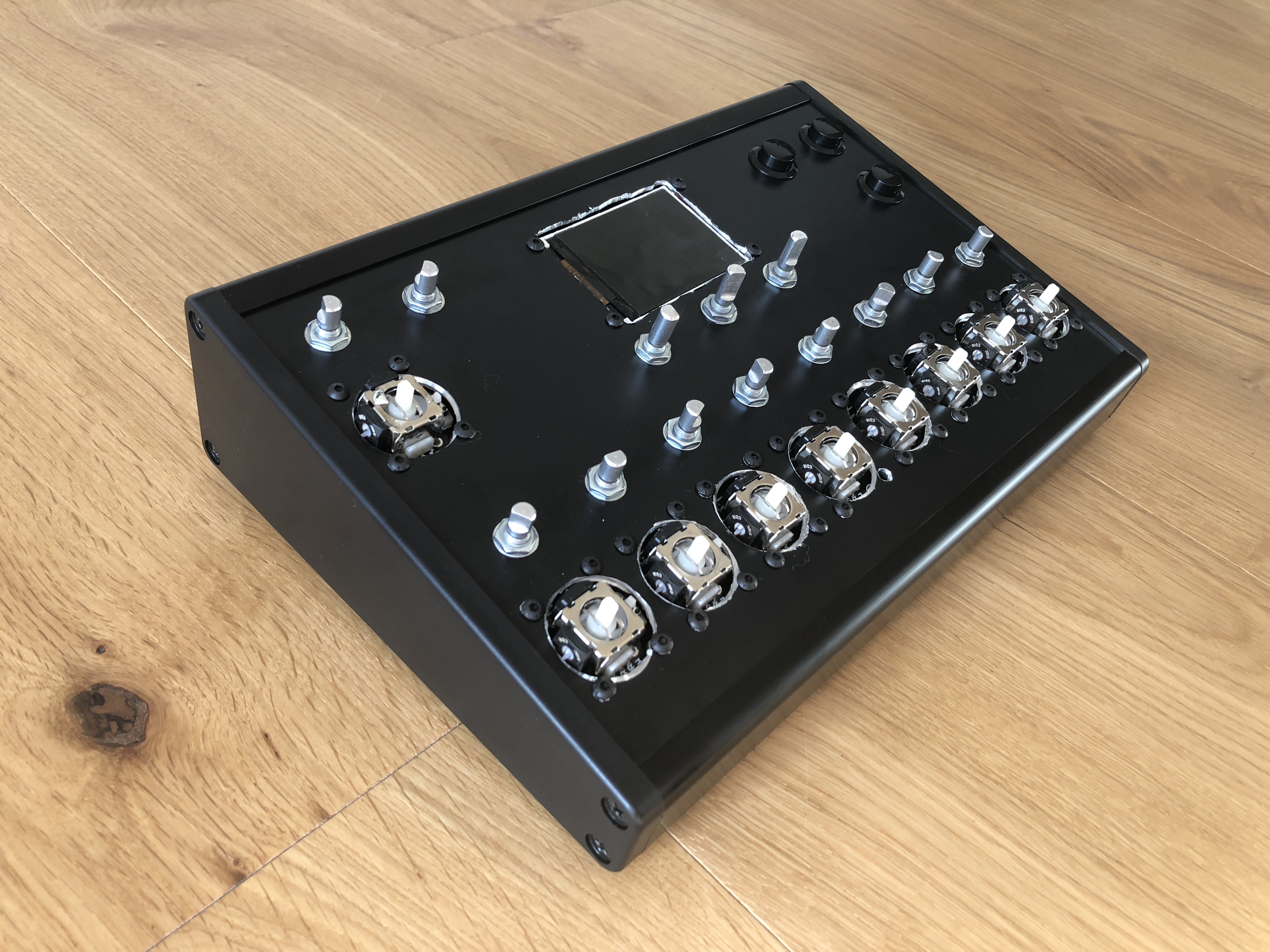
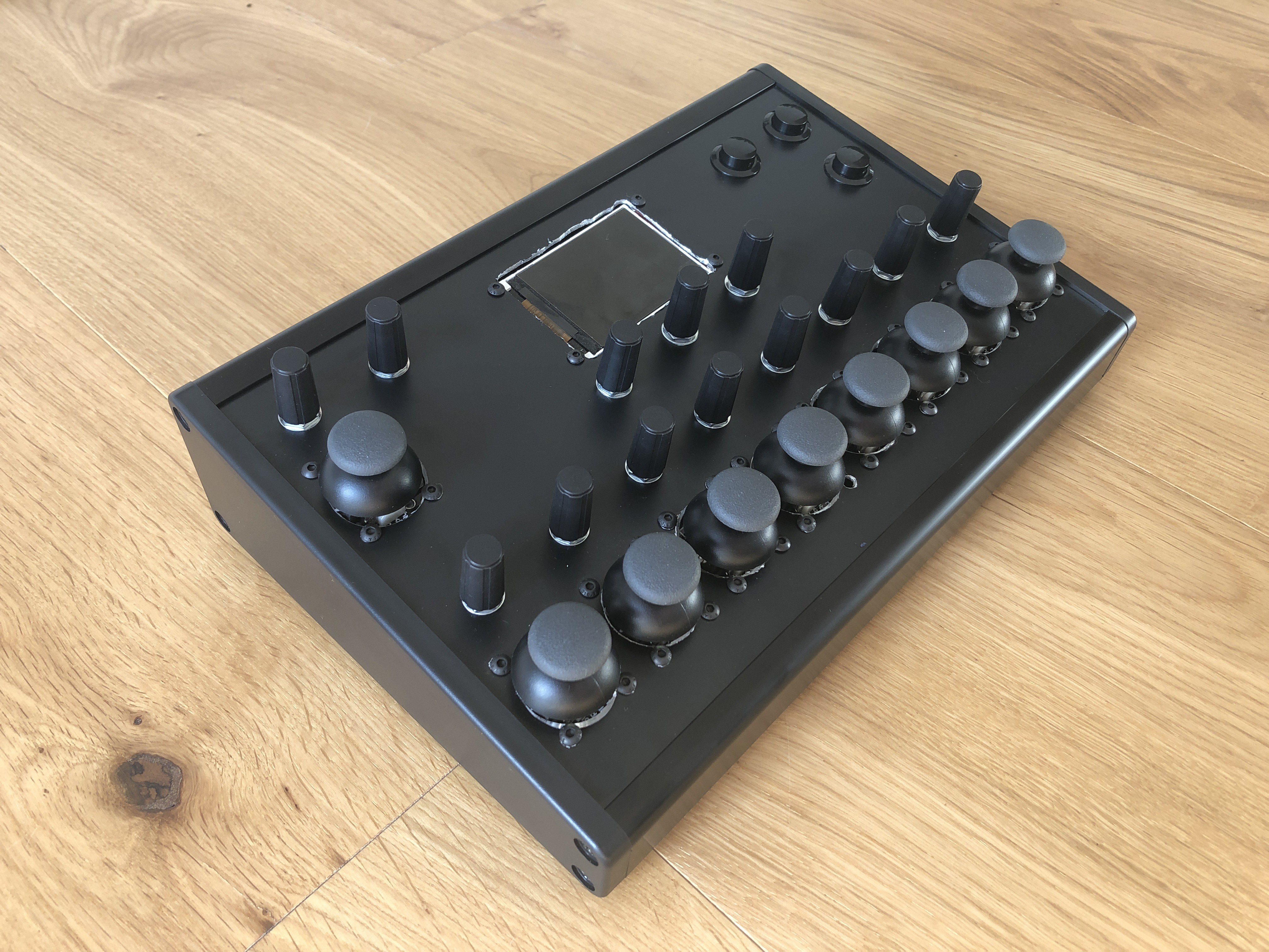
Over the past weekend I attached the majority of the controls to the enclosure, and the device is now starting to look like a working MIDI controller (from the outside anyway!).
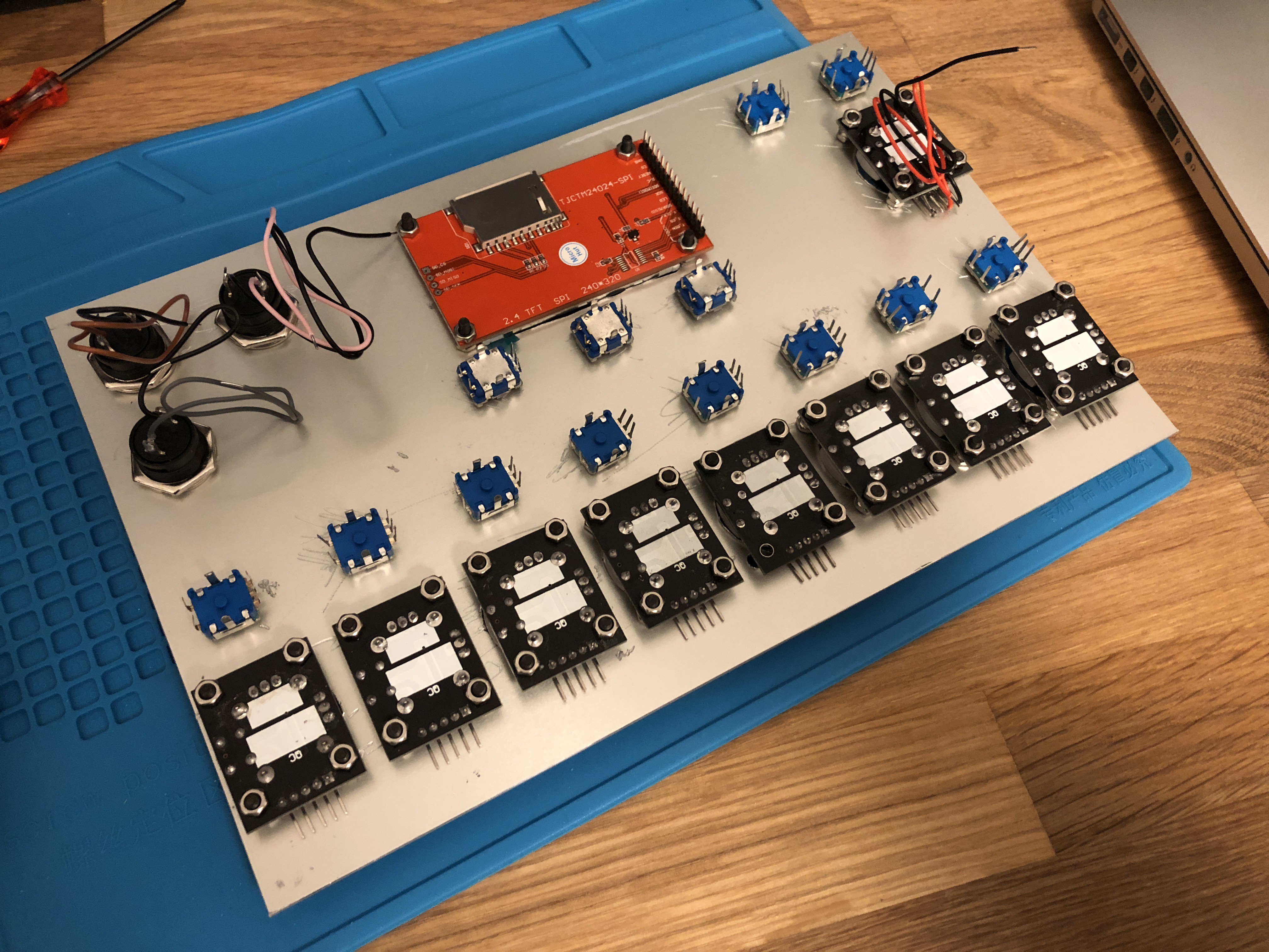
Parts
These are the parts I've used:
- 13 x Rotary Encoders. The encoders I'm using are 20 click indented, and have a switch on them which the majority of them will use.
- 9 x Thumb Joysticks Development Modules. These come on their own PCB with mounting holes which make it easier to mount the joystick to the panel. These joysticks have a switch on them, but as mentioned in a previous log I won't be using them here.
- 3 x Black Momentary Push Buttons.
- 1 x 2.4" 320x240 TFT LCD with a ILI9341 controller chip.
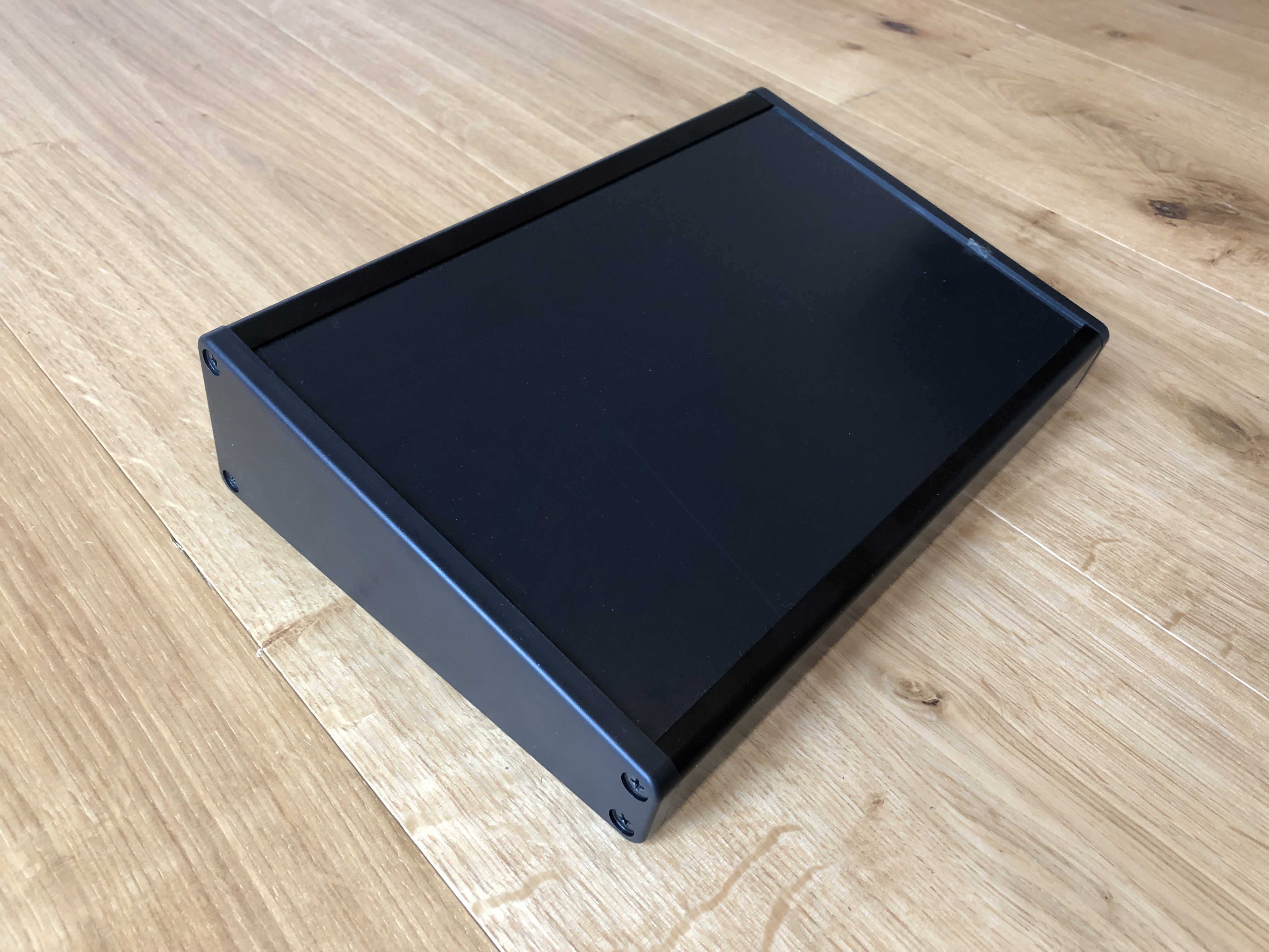
- 1 x Takachi Electric Industrial CF27-18BB sloped enclosure.
Enclosure Choice
I chose to use the Takachi Electric Industrial CF27-18BB enclosure for the following reasons:
- The sloped design of it should make the controller more usable
- It's almost the perfect size for the controller
- The panel faceplate can be easily removed from the frame, making it easier to drill holes in and makes it easily replaceable if needed.
- You can access the inside of the enclosure from either the left side, right side or bottom; this will be handy if needing to repair the device once all put together.
- Aluminium is more robust than plastic
- Comes in black
Panel Drilling Template
Unfortunately I'm not yet knowledgable in using any CAD software for producing technical drawings, so for creating a template for drilling the enclosure I used a probably-questionable alternative - Photoshop. Whilst using Photoshop probably made this process harder than it needed to be, it got the job done. Also as I'm only using this drawing as a manual drilling template, as opposed to a technical drawing for a CNC routing machine, it doesn't matter too much at the moment. See below for the final template design both with and without gridlines:
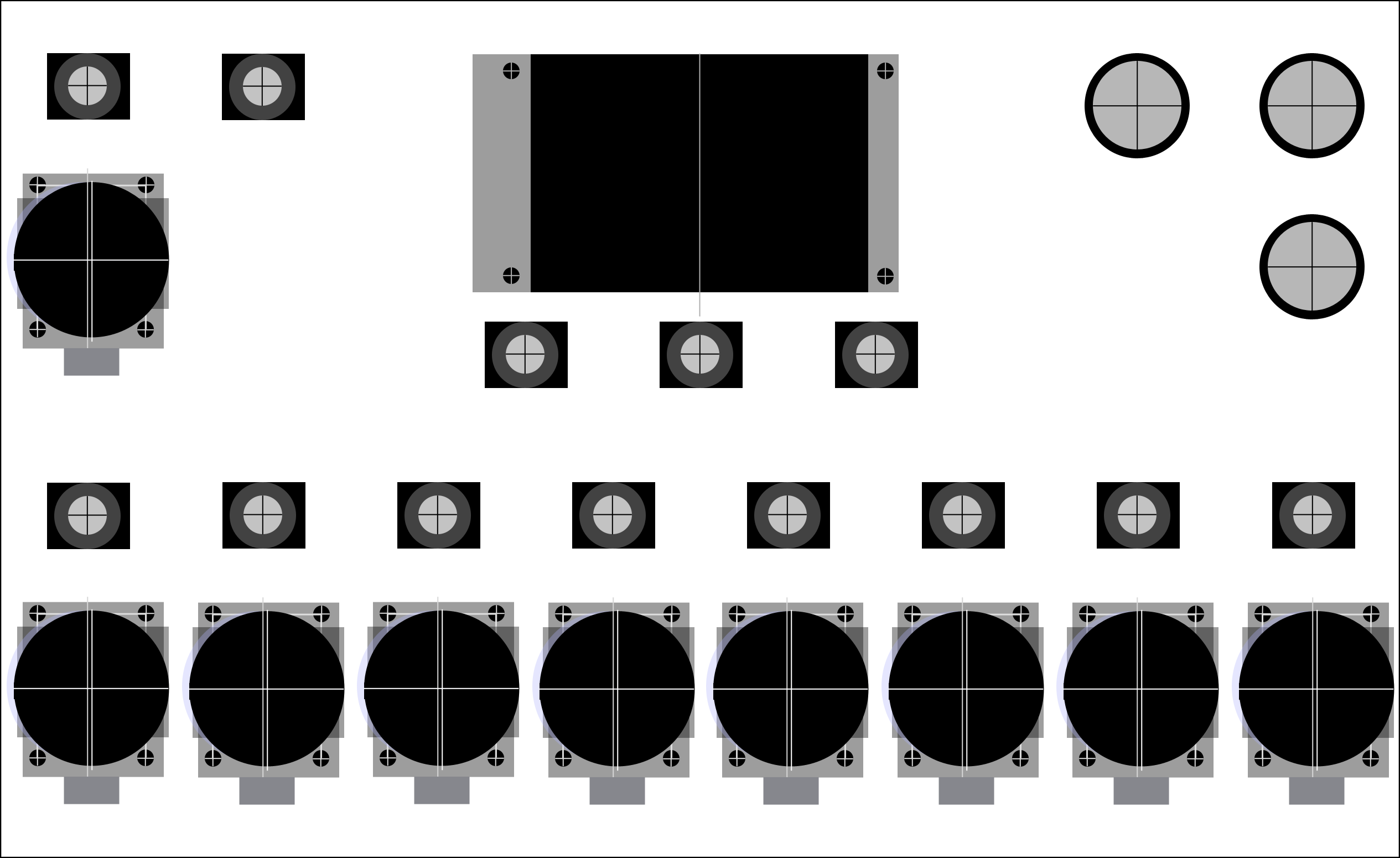
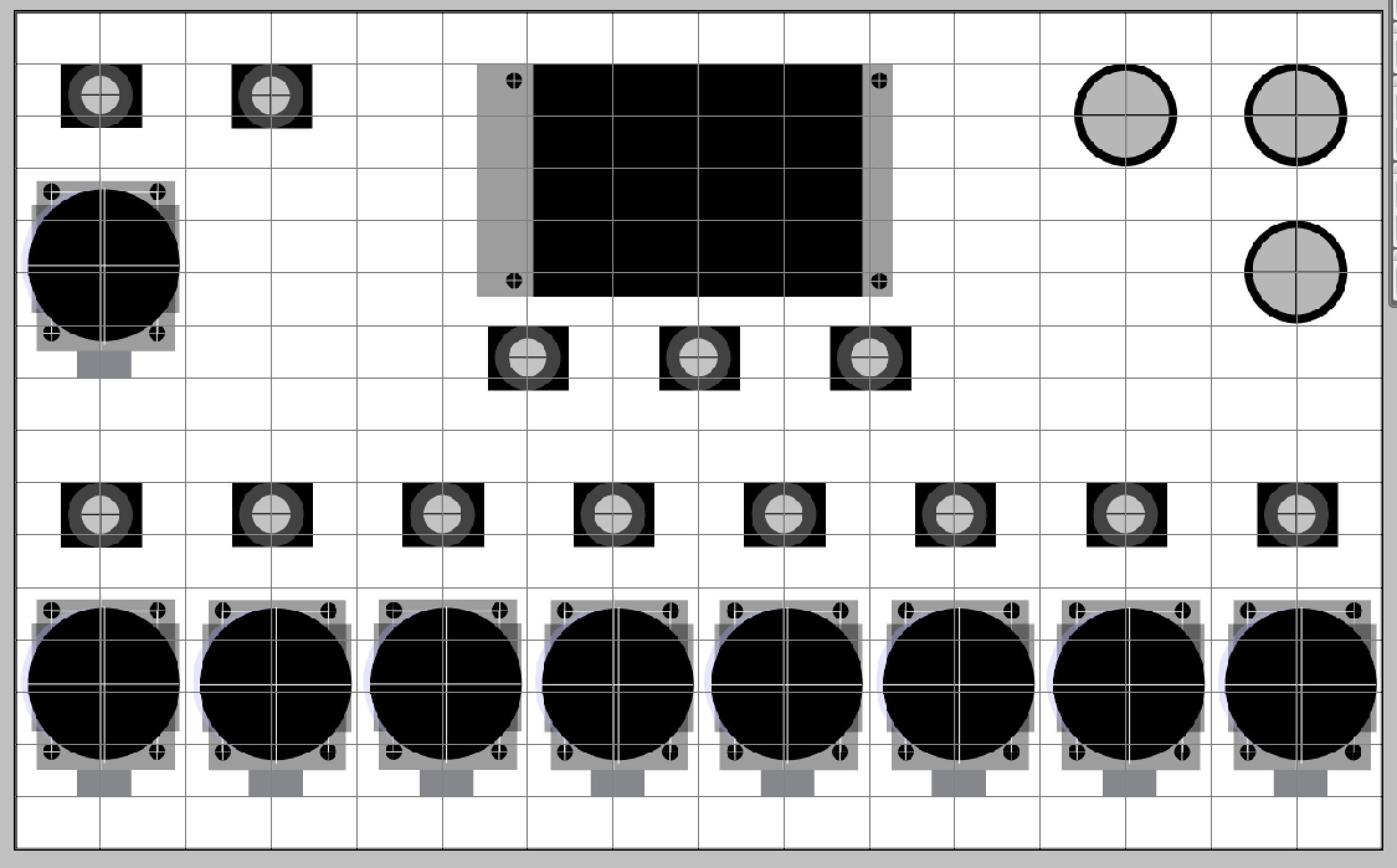
Creating the template for the joystick module was the trickiest part here, as the actual joystick isn't central on the PCB meaning the hole for the joystick is not central between the mounting screw holes.
Drilling the Enclosure
To make holes to attach the controls to the enclosure I only had a drill and a Dremel at my disposal - no access to a CNC routing machine (or a CAD drawing to provide to one!).
Below are some photos of the process:
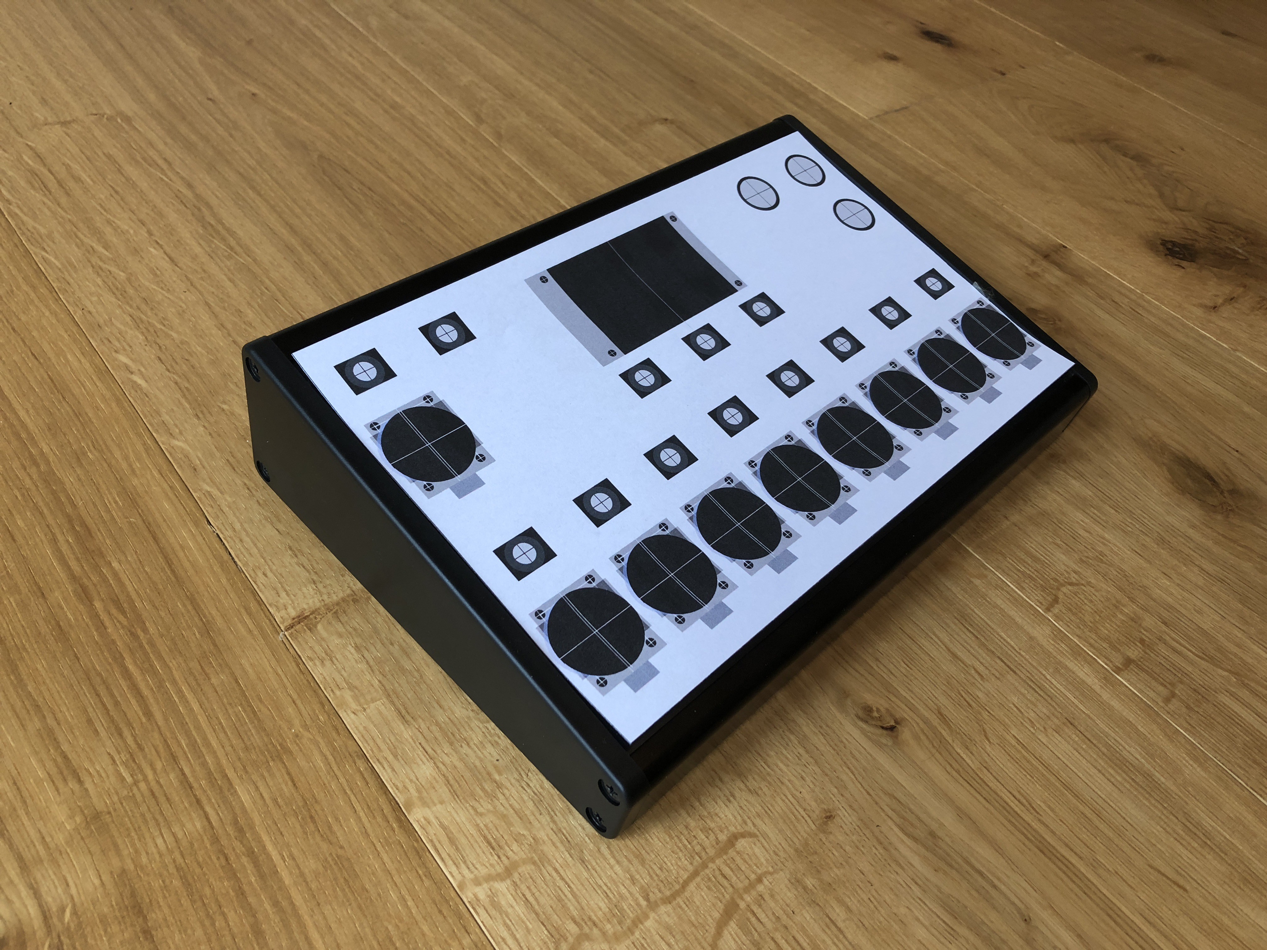
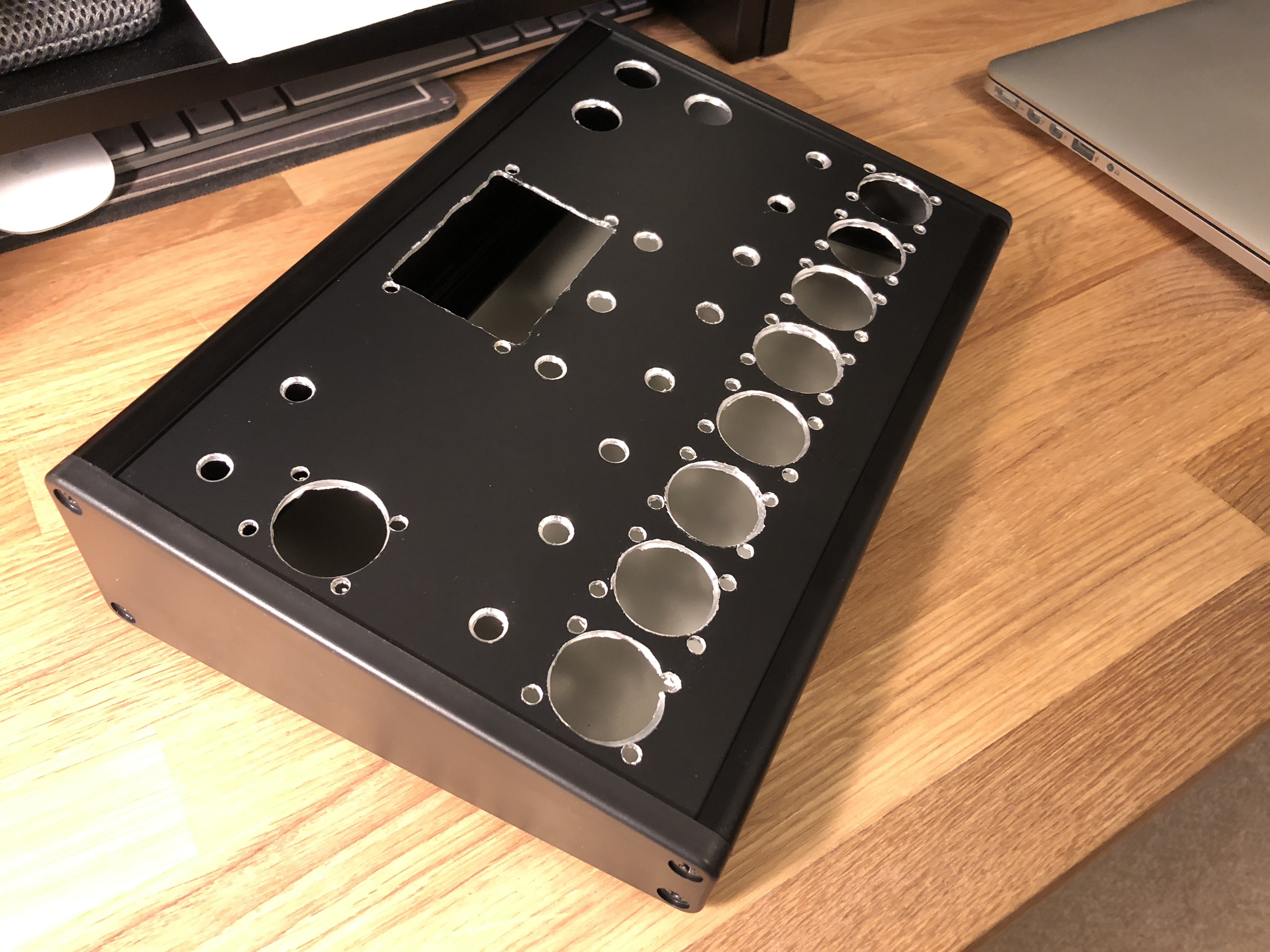
While it's not the neatest drilling job, overall I'm happy with how it came out. I'm not too happy with the messiness of the hole for the LCD (cutting out a rectangular hole with just a drill and Dremel was particularly tricky), however I'm going to attach some kind of laser cut frame to the top of the panel to tidy this up.
Hole sizes for the controls:
- Joysticks - 27mm
- Encoders - 7mm
- Buttons - 16mm
- Mounting screw holes - 4mm
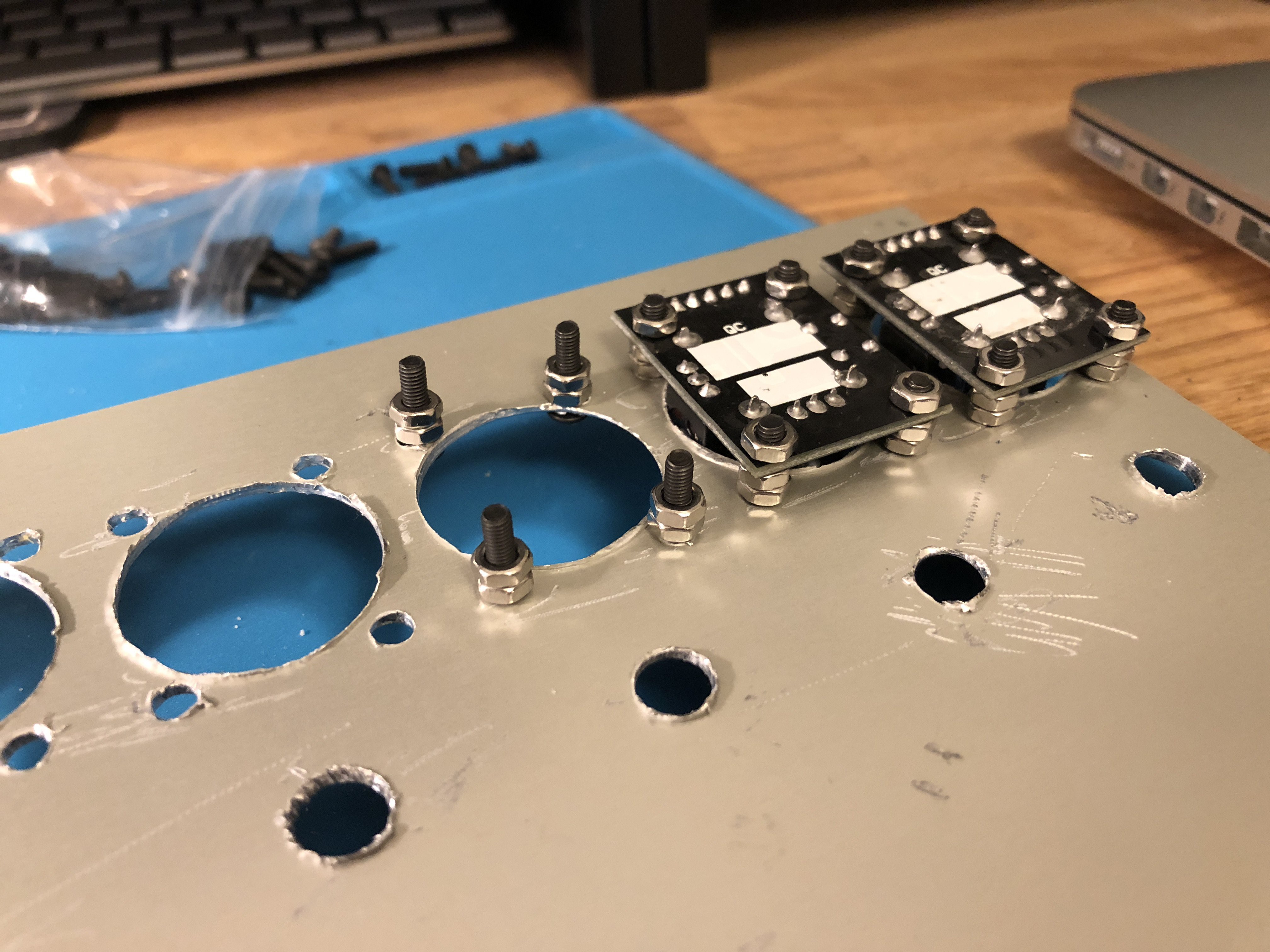
Attaching the Controls to the Panel
The controls are attached to the panel in the following ways:
- Joystick modules are attached via 4 x 12mm M3 screws, with two nuts on each screw used as spacers between the top of the PCB and the underside of the panel (see photo below). The spacing nuts were needed due to connectors and other parts being in the way.
- LCD module is attached via 4 x 10mm M3 screws with a single nut on each screw used as spacers, like with the joystick modules.
- Encoders are attached via nuts attached to the shaft on the topside of the panel
- Buttons are attached via nuts attached to the shaft on the underside of the panel
What's Left To Do
I've got a few things left to in regards to attaching controls to the enclosure:
- Add a laser cut frame around the LCD to tidy up the messing panel cutting
- Attach a USB socket to the rear of enclosure
- Possibly replace the knob caps to something smaller
Discussions
Become a Hackaday.io Member
Create an account to leave a comment. Already have an account? Log In.