 Xasin
XasinThere's an important lesson for everyone here at the bottom, please give it a read!
This morning I was greeted by a lovely message from Aisler, telling me that my project had been bought by a couple of people!
That isn't fully unexpected, as I was told a FabLab was working on implementing my Lasertag Project as a small workshop course, but it still comes with a problem:
The PCBs uploaded to Aisler are faulty
No, it's not a major problem, or something that requires the people that did buy them to throw them away.
The problem is the following: In the top right corner of the front of the PCB, a trace coming from the RESET and GPIO0 buttons is shorted against the ground pad.
The good news is that it is easy to cut with a scalpel, and the rest of the PCB is functional - so for those that did already buy the PCB, don't worry, it will still work!!
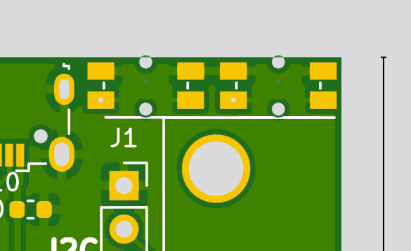
The bottom pads of the buttons, where you can also see the vias, are the "output" pins. They should not be connected to ground, but they are. Cutting them with a scalpel will resolve the issue, and you can not damage anything by accidentally leaving the fault in. If the ESP32 does not boot up, but 3.3V is present, this is likely the problem.
Other things worthy of note to get it running:
- You will need a set of 0603 resistors and capacitors to solder up the set. I did not include them in the Aisler parts list, because those are components I always have on hand from a lot of other projects myself.
- You will need PMBT2222A (or similar BEC SOT-23) transistors for the IR LED and vibration motor (I always keep those on hand as well, they're fantastic little BJT transistors <3)
- You will need a 480mAh LiPo battery, preferrably with built-in protection. For germans, I can highly recommend eckstein-shop.de for those
- You will need an Antenna for the ESP32, preferrably a PCB antenna with sticky backside to mount in the casing.
- For the external vest detector piece, you will need 40kHz VISHAY IR Receivers, as well as a bunch of WS2812 LEDs to chain together. Oh, and a D-SUB cable, the ribbon cable mounted ones are great!
- You'll also need a I2S Amplifier chip. The MAX98357a is perfect for the job!
My lesson: Always be vocal about the state of the project
I feel a bit bad for the people that bought the PCBs and now have to go through the process of reworking them.
If I had been a bit more vocal about the state of the project, i.e. mentioning that the PCB needs reworking, the Aisler parts list isn't fully complete, then maybe people would have waited a bit longer, or would have been more prepared to deal with these issues.
The way I made it seem was that the project was fairly easy to build, and ... That's my mistake.
However, this should also be a lesson to anyone trying to buy or build projects here on HackADay:
Nothing will be perfect. Mostly, we're all just a bunch of nerds having fun with these things - or at the very least, I know I am!
There will be undocumented flaws, incomplete parts lists, or other little quirks in the process that the person building them dealt with and ... Never really wrote down, because it didn't seem like a big deal.
As a maker, the best we can do is to put a huge "WORK IN PROGRESS" above the things that aren't quite ready yet.
And as the person trying to build it, we should always make sure the project is replicable: Please, ask about the status of PCB etc.
If the maker says "The PCB needs a bit of rework", then that means it's not ready yet.
Continue if you wish, but at your own risk to deal with all those little quirks the Maker left in.
Discussions
Become a Hackaday.io Member
Create an account to leave a comment. Already have an account? Log In.