T. B. Trzepacz
-
Speaker Mounting Ring
10/05/2018 at 14:05 • 0 commentsI got tired of the speaker flopping around and the metal bits on it threatening to short circuit stuff, so I designed a 3d printed plastic mounting ring for it. Here is the view from Cura.
![]()
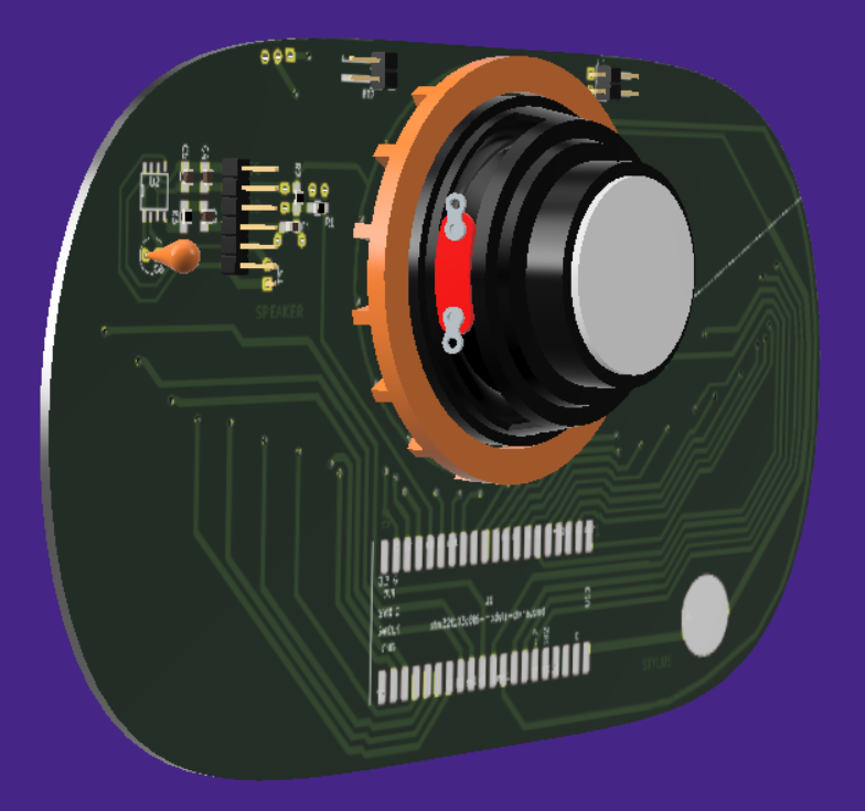
Here is a 3d rendered view of how it mounts on the back. I colored it orange so that it would stand out, but the real one is designed to be unobtrusive.
That's not a model of the real speaker, just the closest equivalent I could find.
Notice that there are gaps spacing it away from the PCB. That's because the real PCB has all sorts of solder and bodge wires on it and I needed some sort of spacer to get around all of that. The production design can use a much slimmer profile.
![]()
And the front view.
![]()
So here is the actual 3d printed output. Came out pretty much exactly as designed.
And here it is in the current prototype. Looks ok from the front, but if you look carefully you can see huge gaps in the bottom and top. That's because it DIDN'T FIT AT ALL! My "solder-glued double width board" is kinda missing a mm or two in the middle where the boards join, probably due to the width of the end mill used to cut the board. That makes the inner diameter much smaller than expected. Rather than redesign and reprint for this one-off test board, I just munged it with nippers until I was able to jam it in. Side effect; the friction fit is ~*REALLY*~ good....
Here is the back view. You can see that the actual connector for attaching the speaker didn't fit either, and I had to actually cut a hole in the ring for the cord to go through. You can't tell, but I also had to cut a bunch of supports down on the bottom because of the various bodge wires that were pushing the ring up to a point where it didn't grip on the inside of the hole. Worse, the spacers that were supposed to go between the raised spots on the PCB ended up right on top of the vias, which were what I really was supposed to be avoiding, I managed to twist it a little bit to solve this, but I should really fix that before I make another one.
Anyway, despite all of the errors, it does the job for now.
I'm trying to make the thing a little more stable before I record my final necessary song video for the Hackaday prize entry. Just a couple of days left!
-
More Hackaday Prize requirements: What does it solve? How is it used?
10/04/2018 at 13:14 • 0 commentsSince I'm entering this in the Hackaday Prize, I have to write up a bunch of stuff I wouldn't ordinarily bother with.
From the rules:
- Discuss the challenge the project addresses.
- Discuss how the project will alleviate or solve the problem that the project addresses.
- Publish at least one (1) image illustrating how the project might be used. This may be a sketch, schematic, flow chart, rendering, or other type of image.
This project meets many challenges.
- Real music synthesizers that let you build your own sounds are kinda expensive.
- This one will be cheaper. The BOM works out at about $15. I intend to sell it for a lot more than that, because I need to eat, but it will still be cheap in comparison to similarly powerful units.
- The ones that are semi-cheap are usually not very powerful.
- I'm going to give you real synthesizer stuff like filters, envelopes, adjustable waveforms, multiple oscillators, etc. You'll be able to save sounds to the internal memory on the CPU. I hope to even allow for a tiny sequencer and maybe a drum loop.
- The ones that are semi-cheap are kinda hard to use.
- This one should be very easy.
- To select a different sound, tap on "Patch" and tap on a key to load that patch.
- To write a patch to memory, tap on "Write" and tap on a key to save over that slot.
- To edit a sound, tap on "Value" tap on a key to select a value. Release for a second, and then tap on another key to change the value to the number of the key. It will play the sound. Tap on "Value" again to stop changing the value.
- To change to a different mode (Sequencer, Drums, Blinky Lights), tap on "Mode" then tap on a key to change to that mode.
- Hopefully all that is simple?
- Having a stylus keyboard arranged as a traditional piano keyboard with at least two octaves of notes means that it is much easier to actually play real songs that sound like actual music that mundane humans enjoy, as opposed to random fart noises and out of tune screeching sounds most often made by non-keyboard synthesizers.
- This one should be very easy.
- A lot of small synthesizer projects require you to have an amplifier or headphones to hear it through.
- This one has a built in amplifier and speaker.
- Not everybody knows that you are an ace synthesizer player.
- This synthesizer is worn as a belt buckle, and a very large one at that!
- It has a giant flashing, spinning LED ring that can be set to perform a light show when it is not performing music. Everybody can see you coming a mile away, and will all be looking at your crotch.
- Synthesizer is attached to the belt in a way that can be quickly and easily removed and used to rock people out in the most efficient manner possible.
- Convention swag badges often look pretty, but rarely do anything useful.
- This one plays music. (You thought I was going to say "goes to 11" didn't you?)
Are those enough challenges and solutions?
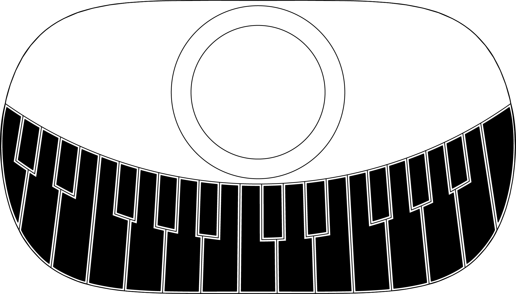
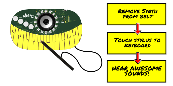
I also need a diagram illustrating how the project might be used. It seems really obvious to me, and I'm not sure how a diagram helps, but ok.
![]()
I hope that does the job! Please let me know if something more is necessary.
The last thing I need is a 2 minute video. But it is after 6am and I'm tired. Maybe tomorrow or Friday?
-
Added License Information
10/04/2018 at 11:44 • 0 commentsSince I am entering this in the Hackaday Prize contest, it requires that one disclose the licensing terms of all of the software that you use in your project. I have added all of that in the Project Details section. I'd rather be writing code, but I am really hoping to get at least a little money from this to continue development, so necessary thing is a necessary thing.
-
Now on Github!
10/04/2018 at 11:07 • 0 comments
So, as the project is currently using the Mozzi audio library, which seems to be available under the Creative Commons 4.0 Share Alike Non-Commercial License, I am sharing the source code on GitHub. In addition, all of the PCB files are available too, although they don't yet include all of the bodges I had to make in order to get them to work.
I suppose anybody could build their own then. Open source and all that.
I actually have quite mixed feelings about that.
I know we are supposed to be all "Rah! Rah! Open Source Forever!" on here, but I am really hoping to sell these eventually, as I've been running a deficit for the last 10+ years. My Nintendo DSi/3DS software "Rhythm Core Alpha 1 & 2" never did earn me anything resembling a proper living, they just slowed the hemorrhaging of money a bit. It wouldn't be fun if it became popular and everybody knocked it off. But I suppose there are lots of other synth projects out there that are open-source that most folks don't bother to build, so perhaps my worries are groundless.
Although, I have to say, I have made it REALLY EASY to build...
I'll have to rewrite all of the Mozzi bits if I want to actually sell any of them; I'm using it for now to get the contest entry done, and it will probably survive through the MAGwest 2019 version; they are a 501c3 and so count as non-commercial, I think.
The code has not been beautified for public consumption, but I have fulfilled the terms of the license,.
Anyway, you can look upon my works and be dismayed here:
Stylish! Trucker Belt Synthesizer on GitHub -
Pulling it all together
10/02/2018 at 07:39 • 0 commentsFinally, having a working keyboard, working sound libraries, and a working LED ring, all that is left is to do some software and pull the whole thing together for a first playable.
I had a sample program that had been running on the breadboard version of the project, based on a Mozzi library demo and the WS2812B test program, sort of mashed together into a big mess of code that made sound and did blinky lights, but somehow it wasn't working on this board, now that everything else was debugged. What to do?
After goofing around for awhile with trying to debug it, I decided that the code really needed a restructuring anyway, and decided to rewrite it starting with the last keyboard test program.
The first thing I ended up doing was rewriting that demo program to be more of a library, for clearer, more concise code. I added function callbacks for key-down and key-up events, and combined the arrays for keys and buttons into one to simplify the loop.
The first thing I noticed was that, when I ran the thing flat-out, there were a lot of key events whenever the stylus was moved. Some debouncing was in order. I ended up implementing a thing called "stable counter" where the state had to not change for awhile before it would trigger the event. I'm not sure this is an optimal solution, but it works for the moment, so I've run with it.
The next step was to integrate the WS2812B library and get it to animate some LEDs. At first, the keyboard had a bunch of problems again, and I was really annoyed. But I theorized that the WS2812B library setup was stomping on some of the configuration I had to do to get the debugging turned off on keyboard pins. So I switched the order of initialization, and the keyboard started working again!
Here is the first test of the LEDs and keyboards working together:
The next thing to do was integrate the audio library. I had determined that the Mozzi Arduino library worked well with STM32, and had run some previous demo programs on the solderless breadboard version of the project.
So I started with the sinewave demo and integrated the code without difficulty. It was very easy then to look at the gain demo and determine how to have it only play the sound when I had the stylus on the keyboard. Finally, I looked at their MIDI demo to see how to get the pitch for the notes.
Now, I know how to calculate all of these things, and I've given talks on such, but what would be the point of using this library if I was going to ignore all of it?
So, I integrated this, added a little bit of decay to the sound and suddenly had a playable monophonic organ! (This is the same video that appears at the top, so there is no point in viewing it again if you've already seen it.)
So there you go! There is certainly a lot left to do, but it is already equivalent to the first models of the stylophone!
-
Debugging the keyboard
10/02/2018 at 05:49 • 0 comments![]()
Trying to make a synthesizer as a piece of swag means a really tight price point that is not well served by having to have a ton of switches for a keyboard, never mind that making a playable keyboard is harder than just putting some switches on a board. Trust me, I've tried!
To solve this conundrum, I determined to use a stylus attached to ground to select traces on a bare circuit board to complete the circuit, acting as a psuedo-switch. This solution was pioneered by the 1967 Stylophone and it's successors, and has been popular in a number of maker projects. This solution requires a large number of pins on the CPU, or else some sort of implementation with shift registers, or multiplexers, or maybe even a resistor network. But we are going for cheap, so we are trying to avoid any components if at all possible.
This really seemed like a no-braiiner; find some free pins on the CPU, attach them to bare PCB, attach a stylus to ground and you are done!

A stylus made from some thick copper wire, some flexible stranded wire, and some heat shrink tube. Well, that wasn't quite it. Although most of the pins worked as advertised, there were still three keys not working. Touching some of them would cause the system to lose USB connection to my PC!
Well, it turned out that two of the pins were actually being shared by the USB port! . Time to cut traces and remap! But I only had one pin free at this point. So I wired one key to the free pin, and the other to one of the pins used by the 4 buttons at the top. Obviously, that is going to be a problem, but I'll solve that later.
The other pin turned out to be attached to some debugging function that I wasn't using. You won't believe how long it took me to find that! So I dug into the STM32duino source and the datasheets and found a way to turn this off. Yay! The A# key now works!
But there was still a problem with the key that I had remapped to the one free pin. What did it turn out to be? A typo in the code.
So, finally, all of the keys were working!
Next up, time to get everything running together!
-
External boards
10/02/2018 at 01:06 • 0 commentsInitially, I was not really sure it would be economical to manufacture in China, and so I wanted to make sure that I could self-assemble these easily and economically. The design was based around commercially available "maker parts" that had cheap knockoffs on AliExpress available in quantity. So the STM32F103C8T6 "Blue Pill" board, 16 LED WS2812B ring, and XM-M125 Amplifier were all chosen.
But after the blinky heart pendant project, I felt more confident about manufacturing in China, so I endeavored to integrate the parts of these boards so that the whole thing could be assembled without the need for daughterboards. In order to do this, I had to actually make sure that I knew what parts were in these boards, and ended up reverse-engineering them to make sure I could get it right.
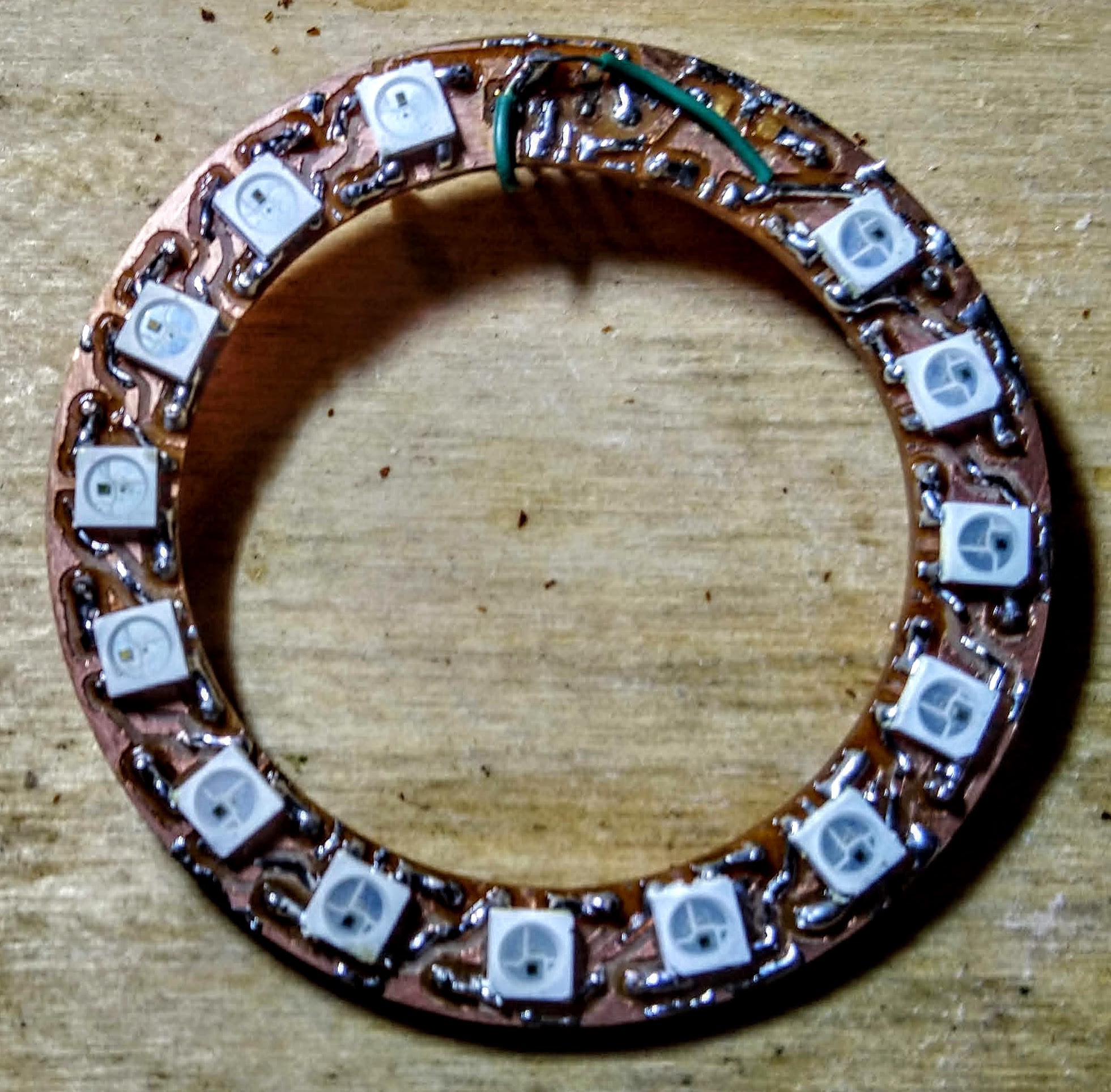
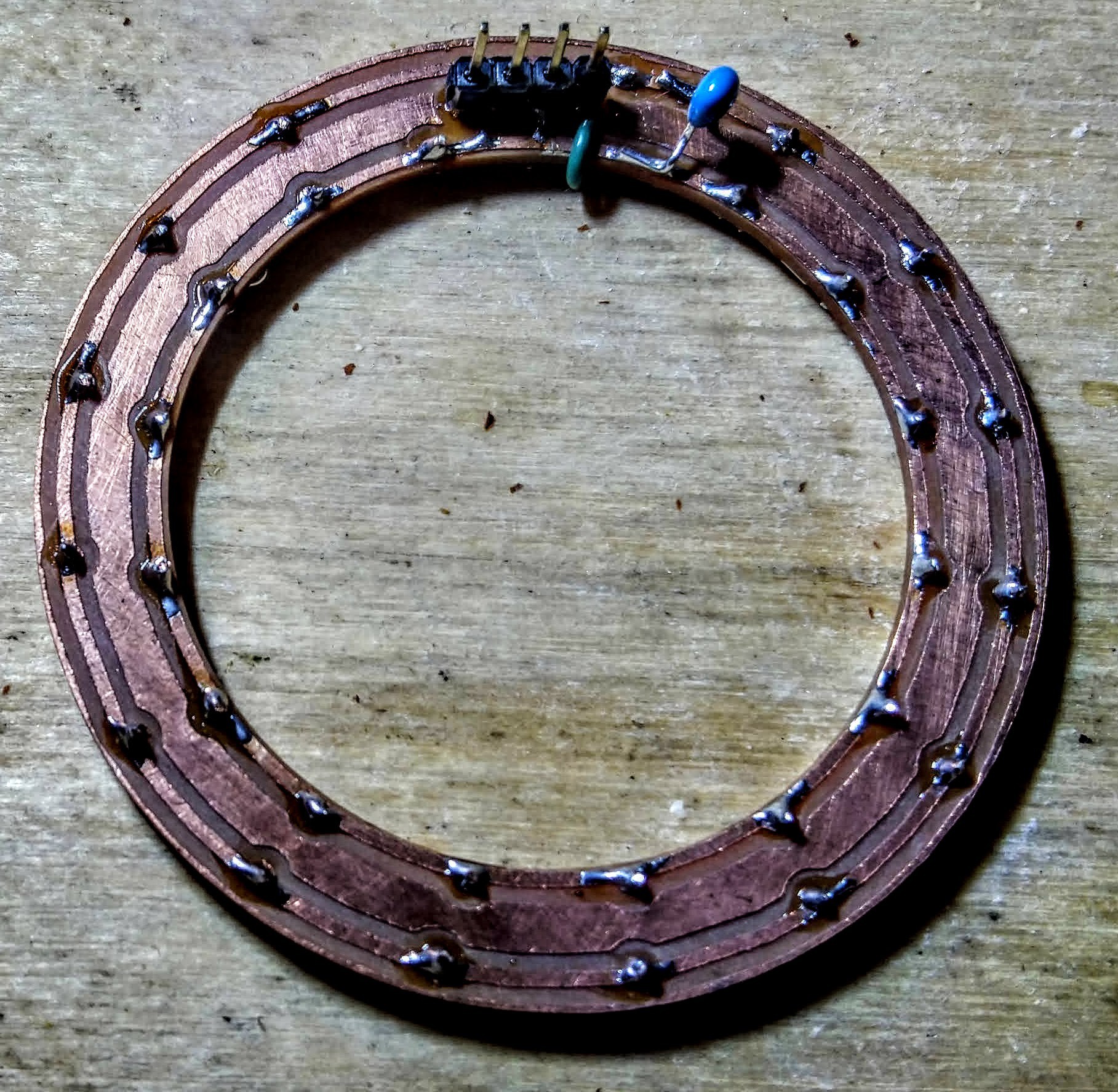
The LED ring
The LED ring seemed pretty simple, but ended up causing a bunch of problems. Splitting the main board down the center of two of the LEDs meant that they were never going to line up. Also, there were vias below the top LED, which is fine for a manufactured board, but is a bad idea when you are milling your own boards that don't have plated through vias and have to solder a wire in each one.
![]()
So, after the main board became such a mess, I decided to split the LED ring off and cut it separately. I had made a place for a pinheader for the commercial LED ring, so I thought by splitting off the design into it's own board I could debug it more easily. (I did have some LED rings that I ordered from China, but they were 12 LED rings because I wasn't thinking about how 16 would give me better capabilities for music stuff.)
So I cut the board, and it had problems. Soldering the header under the LED didn't work as well as I wanted, and I had a terrible time soldering the first few SMD LEDs, and they ended up misaligned. In trying to correct them, I think I overheated the first LED. It didn't work.
I found out that the LED ring was supposed to have a capacitor on the power leads for every LED. I didn't want to waste 16 caps on this bodgy board, so I just added one to see if it helped. It didn't seem to make much difference, but I did notice that the board would kind of work if I put some stress on the connector, which led me to the realization that the solder joints for the pin header that were under the LED just were not making connection.
So I added some bodge wires for those vias, but I was still having troubles, so I desoldered the first LED (taking some traces with) and bridged it. Now it was working, but the 2nd LED seemed stuck on. So I desoldered that, intending to replace it, but it took a ton of traces with it, so I ended up bridging that too. Eventually I got it working.
![]()
![]()
So my 16... 14 LED ring was finally working. I suppose with some time I could bodge together something to get the first two LEDs back in, but I decided that I should get the other aspects of the project moving and save LED stuff for the do-over on the full board.
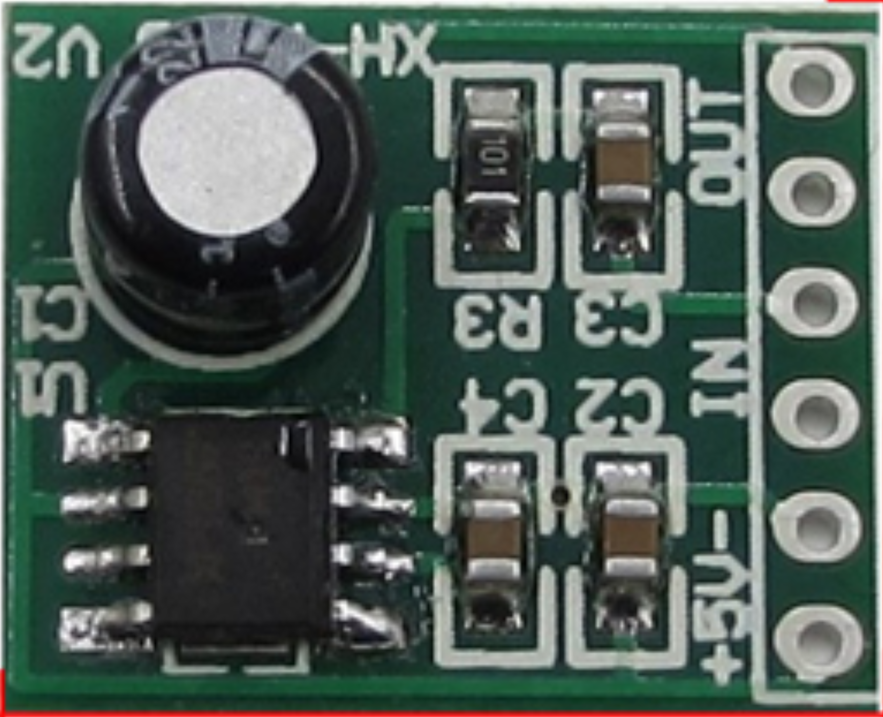
The amplifier board
![]()
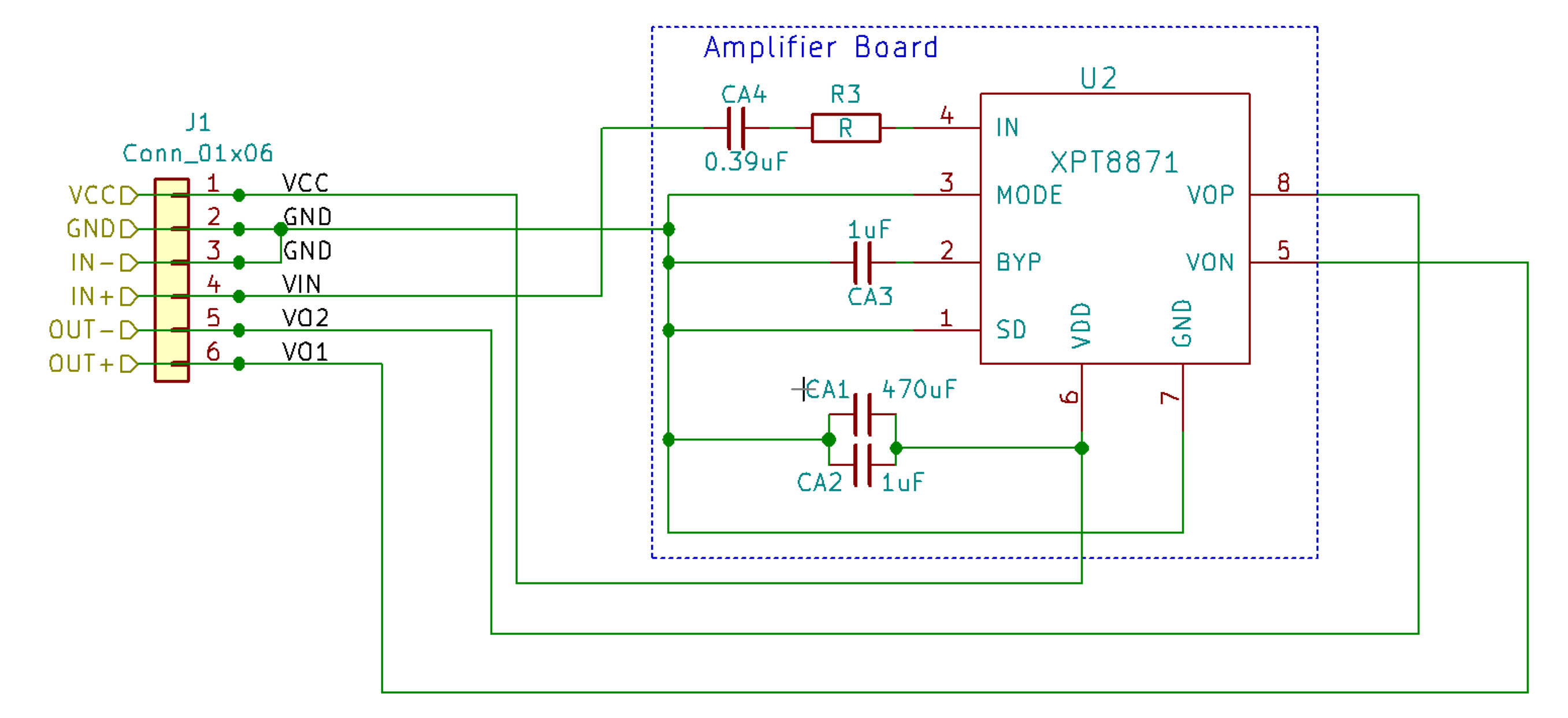
The amplifier board was much simpler. Although the circuit didn't quite match what they had on the manufacturer's AliExpress page, between that and careful examination of the board I was able to work it all out.
![]()
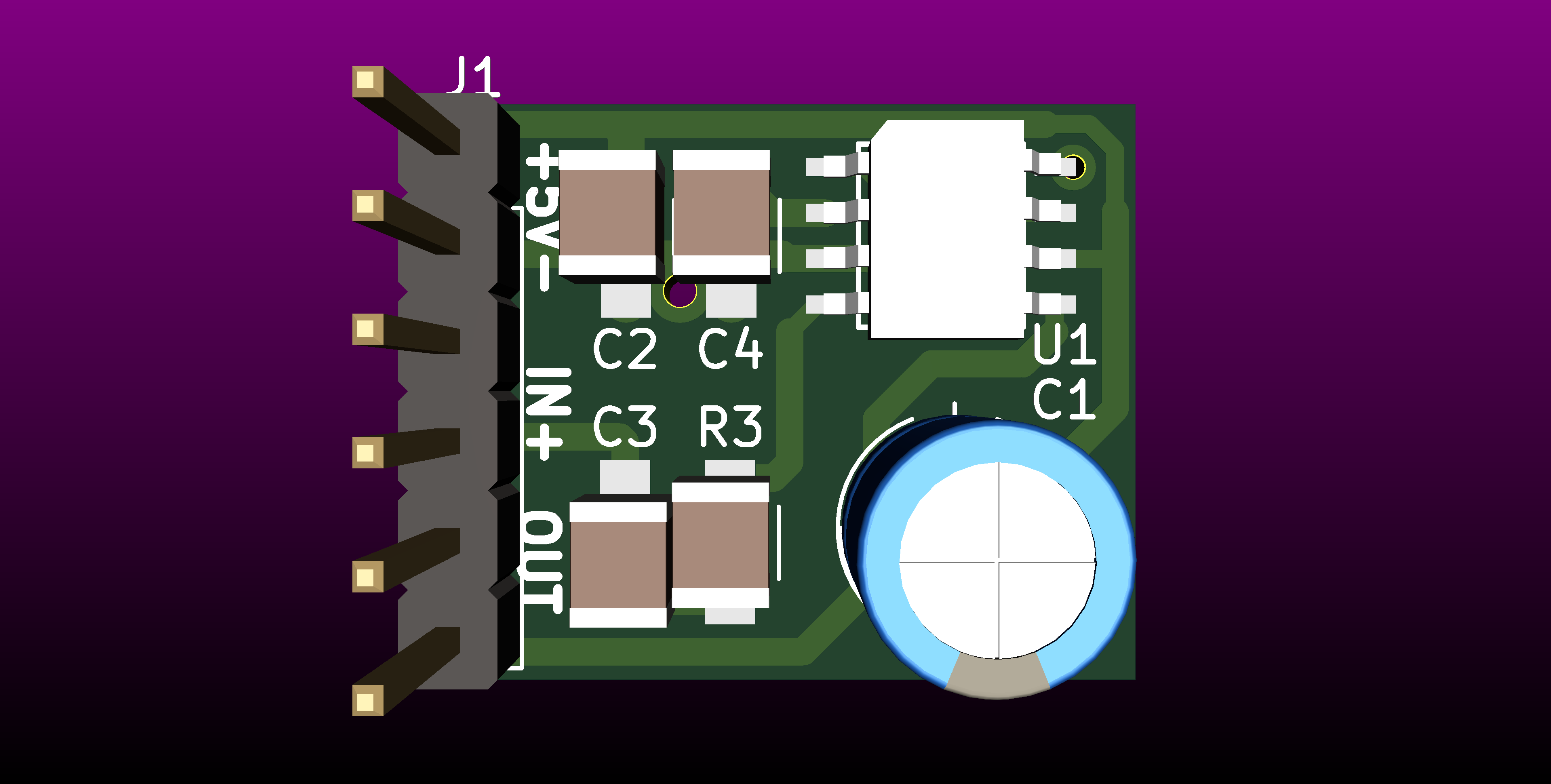
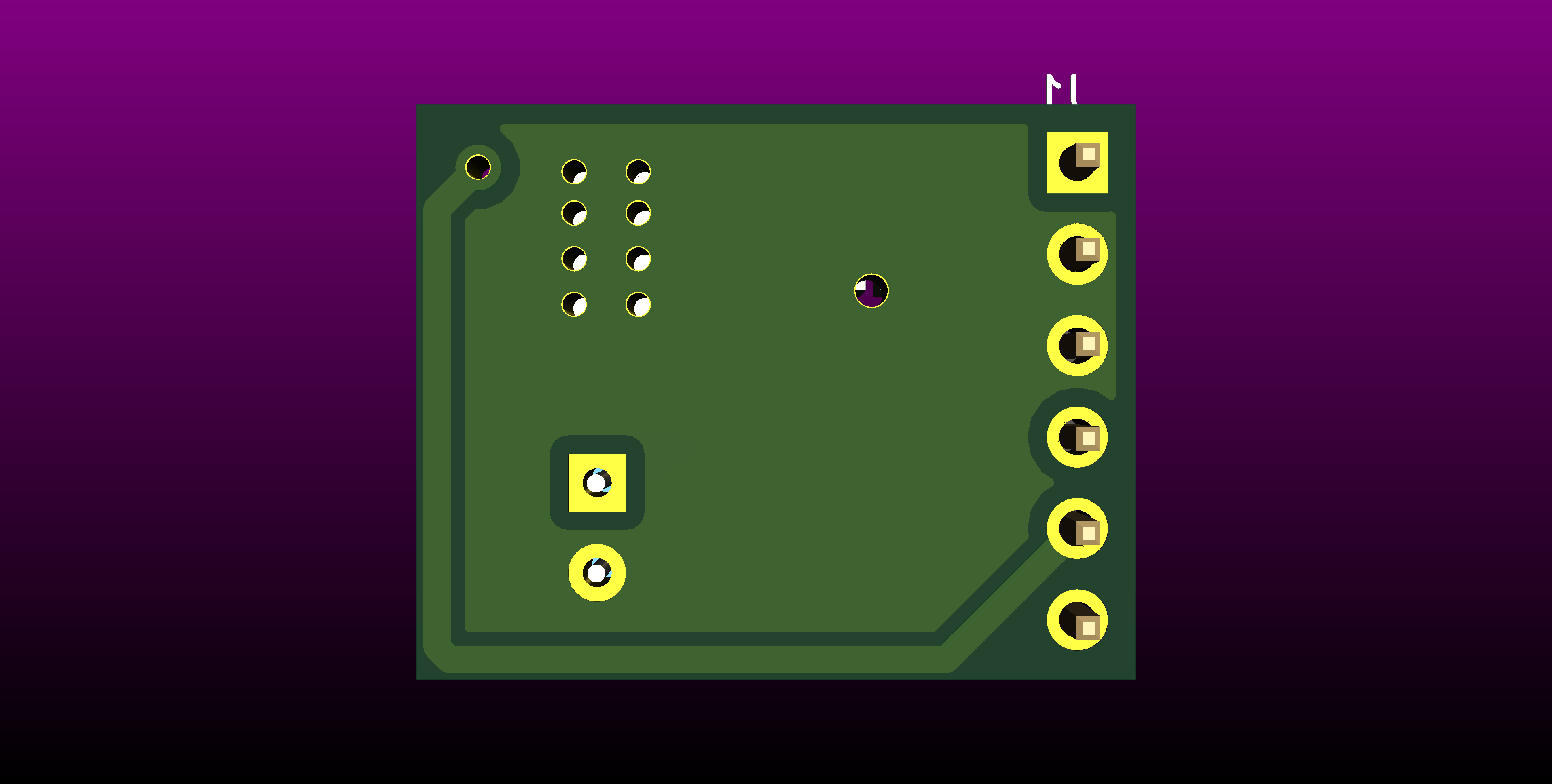
![]()
![]() I haven't actually tried building this yet, so the current circuit just uses the commercially available version. At some point I need to order the XPT8871 amplifier chip so that I can test the version that made it onto the actual project PCB.
I haven't actually tried building this yet, so the current circuit just uses the commercially available version. At some point I need to order the XPT8871 amplifier chip so that I can test the version that made it onto the actual project PCB. -
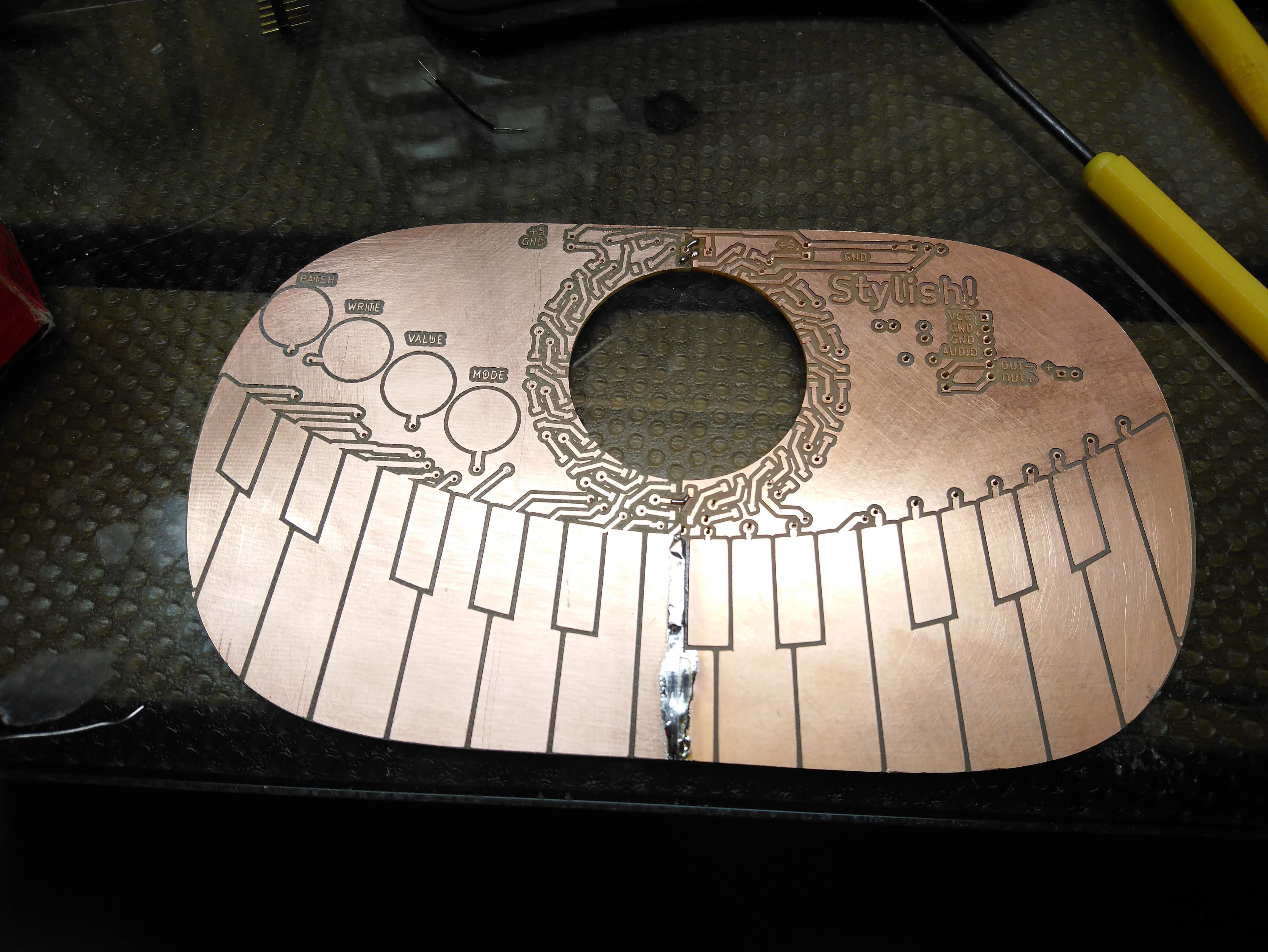
Making a PCB that won't fit in the Othermill
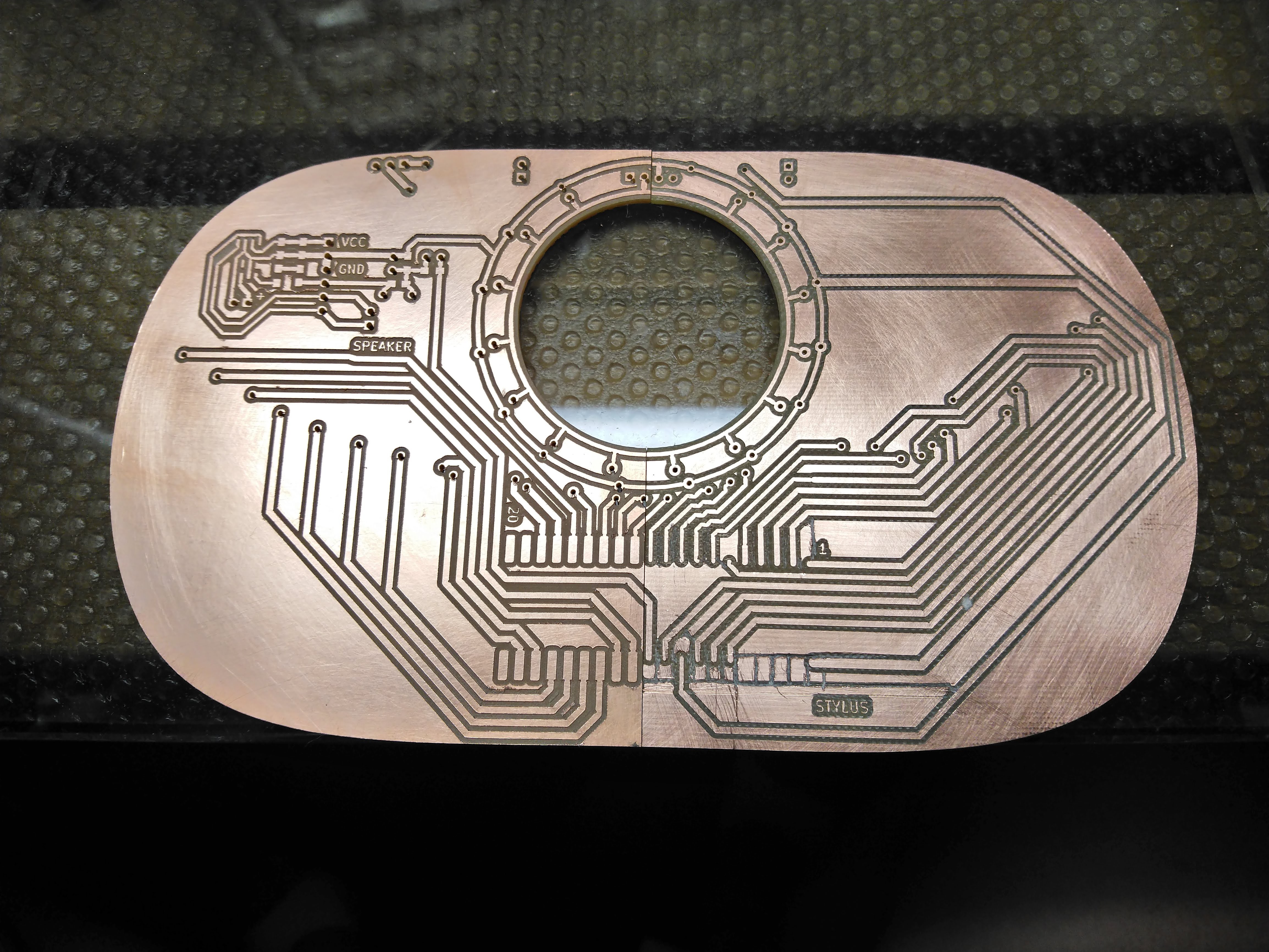
10/01/2018 at 14:17 • 0 comments![]()
So, my home mill will not cut a board larger than 4"x5", and this board is 7"x4.0". Furthermore, the only piece of FR4 PCB material I have left is 4.5"x6.5", so not quite big enough to cut this. I suppose I can split it into two boards with a nasty join in the center, but I don't have enough material of the right shape. Obviously, I can send out for boards to be cut, but it takes weeks to order from China (or super expensive from the US) and I generally like to cut and test at least one before I send out for them.
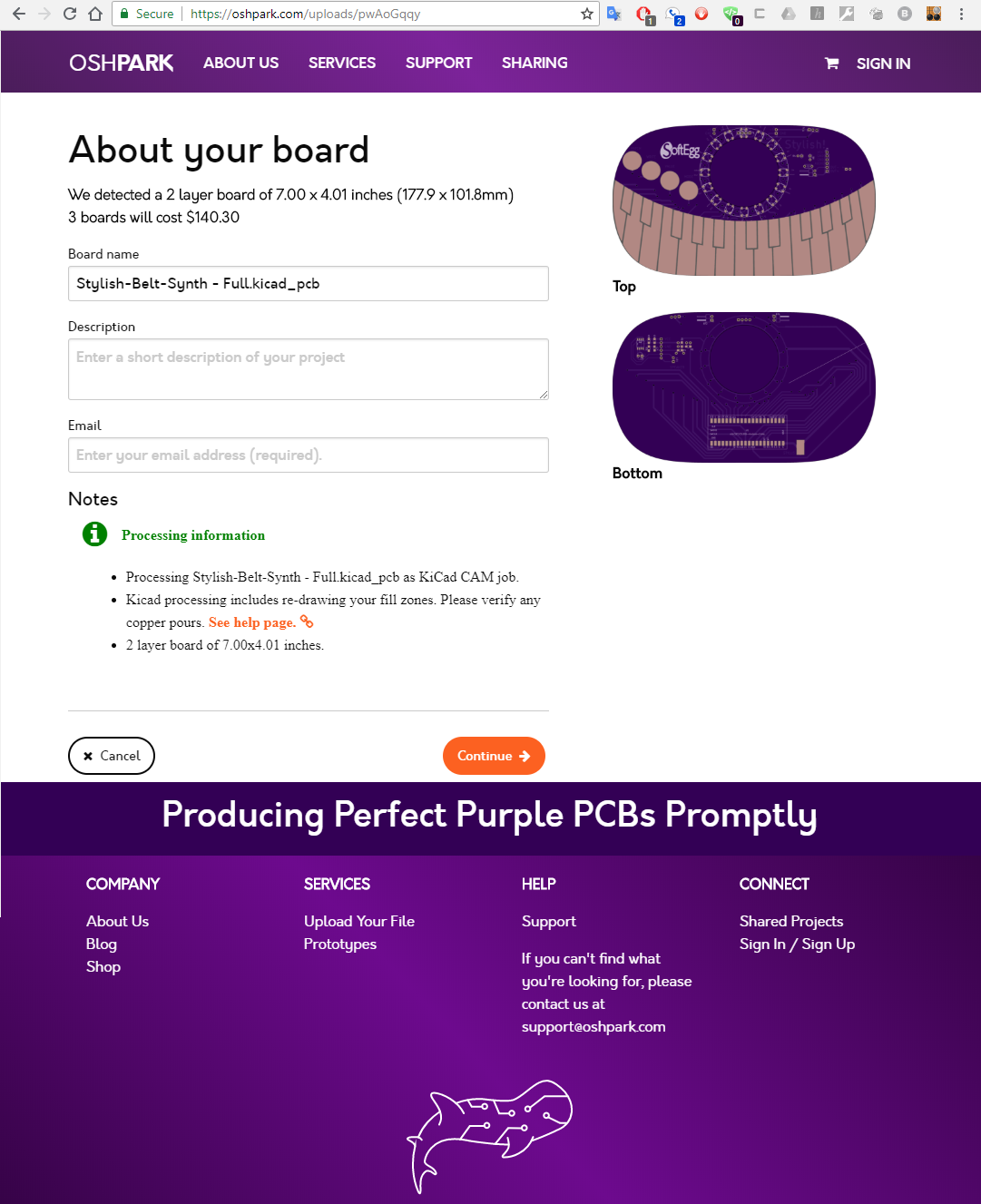
I looked around at quotes. Everybody loves OshPark! Let's try them!
![]()
They want $140 for my board. That is a big NOPE! And I'm not ever sure shipping is included in that!
What about PCBway?
![]()
That's less than half the cost, and includes shipping! Much better! Delivery would take awhile tho.
Who else?
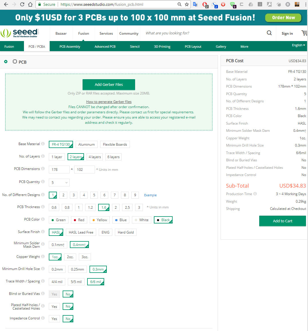
Folks like Seeed Studios. How are they?
![]()
That's like 1/4 the price of OshPark... but wait, no shipping. Assuming shipping is the same as for PCBway (~$20) then we are still 1/3 the cost of OSHPark, and $10 lower than PCBway. Can we do better?
![]()
Yes, yes, we can. Again, probably add $20 for shipping, but $46 vs $140? Yeah, this is probably as low as we are going to go.
But I still want to debug the board a bit before I blow $50, especially since I didn't have the client on board for expenses again yet. So I determined to cut the board in two halves on my Othermill.
I was out of PCB blanks, so I ordered some from eBay. But the first one I ordered from turned out to be on vacation and couldn't deliver quickly, so I ordered from somebody else for slightly more money. And then I realized a few days later that you really aren't supposed to use FR4 on the Othermill, only FR1. FR4 is fiberglass and not good to breath, and also supposedly bad for the mill. So I looked around for FR1 and determined that only Bantam Tools (the new name of Othermachine Co., maker of my Othermill,) sells them, so I ordered those.
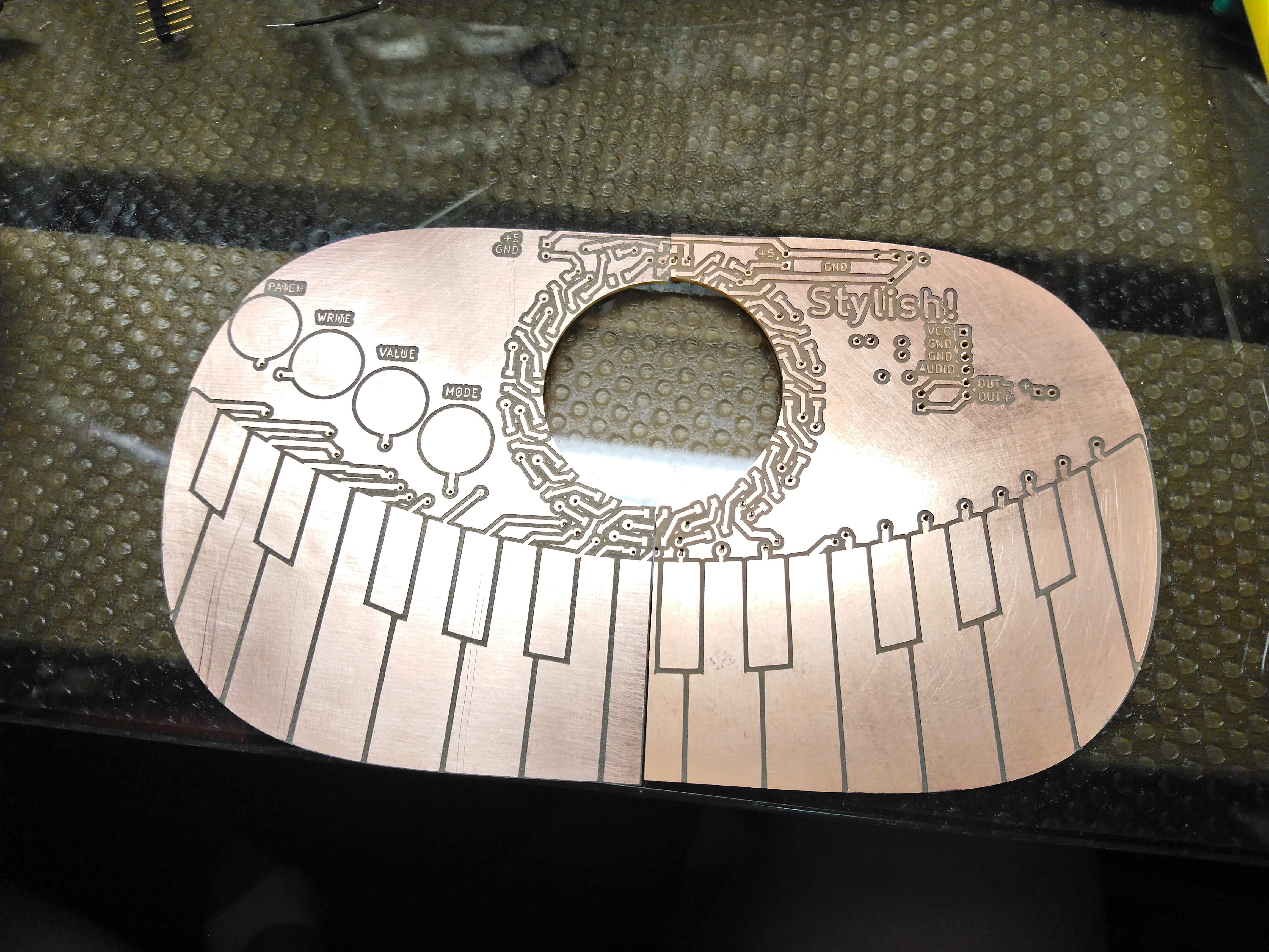
Finally, I got impatient and went to Fry's and paid way too much for some FR4 blanks and got it done.
![]()
It looks lovely, but there are already issues...
![]()
In order to split the boards, I basically had to copy the PCB file in KiCAD twice and then delete half of the board in each one. Trying to line up traces and footprints that go over the edge is pretty tricky, and I had to do a lot of hand editing of the raw text data to split the keyboard footprint properly. It seems that things got a bit misaligned in the process, especially for the two WS2812 that were split across the two layers, and for the bottom of the keyboard. I probably should have modified the border so that the LEDs wouldn't be cut in half. Good to know for next time.
Even worse were the mistakes on the bottom board.
![]()
The entire footprint for the processor was somehow deleted, and I didn't notice until I had cut half of the board! So I had to do a lot of janky rework to get it to the point where non-connected pins wouldn't short out. Furthermore, the connection for the stylus also seems to have disappeared. I fixed stuff up for the second half (on the left), but the right is a huge bloody mess.
Even after rework, there were tons of problems with this board. The top LED just was not going to fit on it's pads. Some vias directly below that LED actually needed a wire soldered into them, which was going to cause problems for the LED. I didn't have the right angle headers needed to mount the Blue Pill microcontroller to the board, so I just bent some pinheaders, but some of the pins didn't quire make contact with the traces due the lack of large pads from the missing footprint. The speaker is just the right size to short out pins on the LED ring.
I'm glad I spend $50 sending out for this board....
-
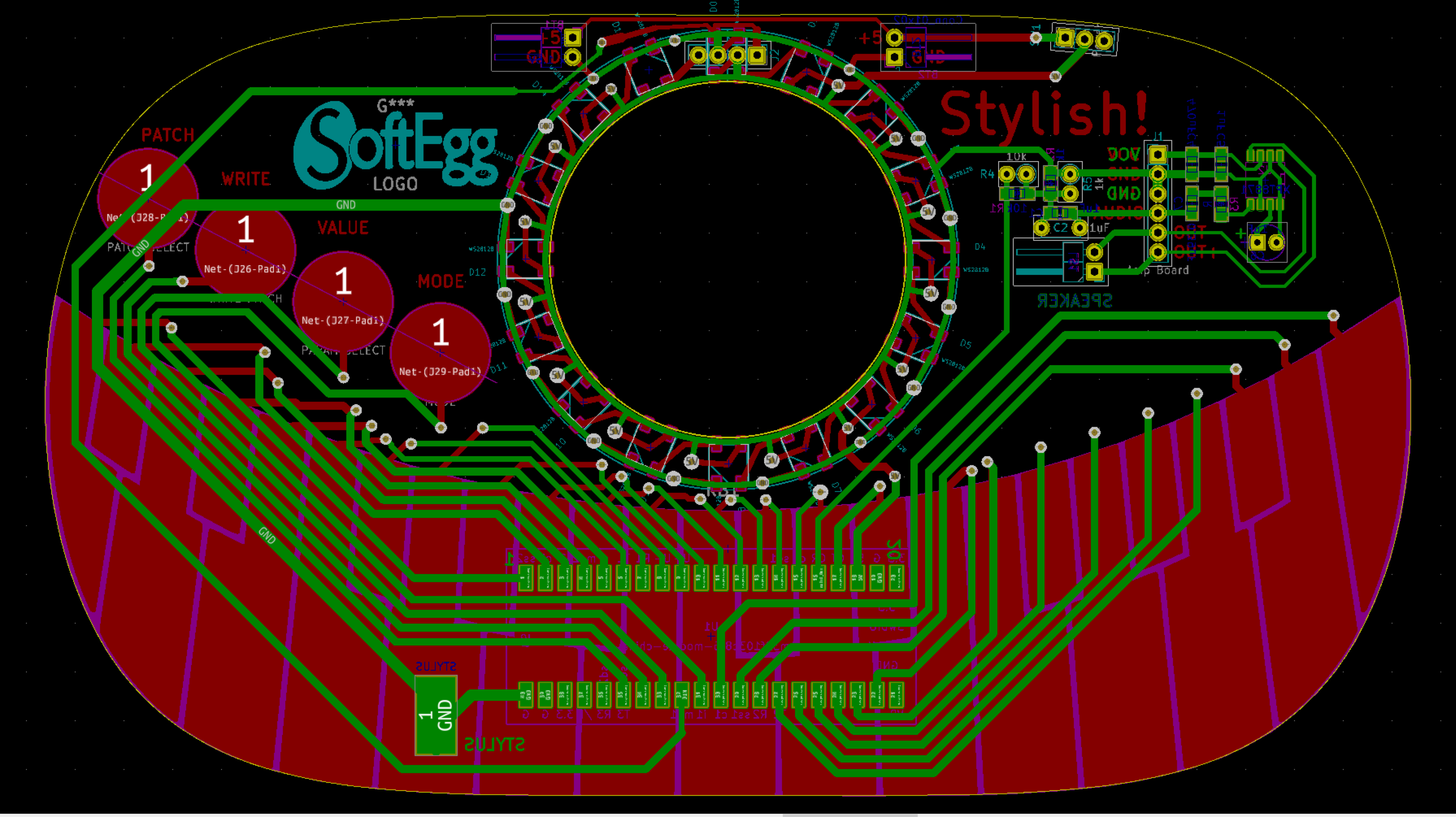
First PCB layout!
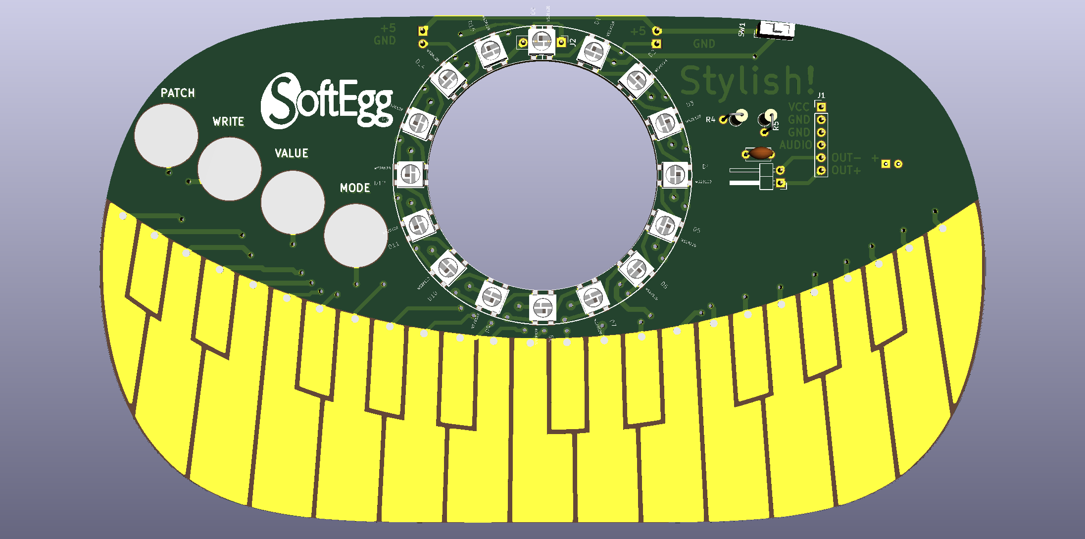
10/01/2018 at 13:47 • 0 commentsHaving Mozzi and WS2812B libraries working and knowing which pins they had to use (due to use of PWM timers / SPI hardware) I could finally design a 1st draft PCB. It is kind of necessary to make a PCB to actually test the stylus keyboard part, anyway.
Fortunately, I'd finished up the rather complicated keyboard layout before I'd stopped working on the synth to make the pendants, so I didn't have to mess around with that again.
![]()
Getting KiCAD to turn a drawing into a filled footprint was tricky, but was finally accomplished by using the "Import Bitmap" option, otherwise known as "Bitmap to Component". It was pretty annoying that I had to take my nice vector art and convert to a bitmap before it could be turned back into vectors again, but despite some trickyness with DPI settings, I eventually got it.
![]()
There are connectors on the board for attaching pre-manufactured LED ring and amplifier boards for easy kit building, but all of the SMD part footprints are there for inevitable factory assembly cheapness.
The STM32F103C8T6 processor is actually the complete development board, available from AliExpress for less than $2. It has to be mounted using two angled pin headers surface mounted on the back of the board, or else via a surface mount 40 pin socket and pin headers soldered to each board.
The speaker is mounted in the hole in the middle of the LED ring... somehow. It is attached via the pin header to the right of it, near the amplifier board.
The power switch is currently designed to be the same one used for the pendants, because I have some.
The stylus attaches via stranded wire to a large SMD pad on the bottom and back of the board. In this design it is tied to ground, and each pin is polled as input to detect which key/pad is touched. A future design might use shift registers to free pins, in which case, the stylus would need to be attached to an input pin.
This design uses ALL of the pins, so there is no room to add MIDI or rotary encoders, or potentiometers or anything like that, unless one started repurposing the programming and USB pins of the STM32, or change the keyboard to use shift registers or multiplexers. -
Getting my blinky on
10/01/2018 at 13:34 • 0 commentsHaving finally settled again on the Arduino IDE as my dev environment, I needed to get the libraries up and running. I was a little afraid that, even with the extra speed of the STM32, the bit banging to support WS2812B leds would eat processor and cause trouble.
So I compiled the standard Adafruit NeoPixel demos and they didn't work at all! Oh noes!
I googled around and found a modified version of that library called Adafruit Neopixel ANDnXOR that seemed to work. But when I tried to make any changes to the code, the timing got messed up and the LEDs got really flickery.
So I googled around even more and found that there was a library by the guys who made the STM32duino environment that I was using. Surely that would work! How do I get it... oh, it's ALREADY INSTALLED BY DEFAULT! The demo is right there, called "WS2812B". And it is pretty much exactly the same as the other two Adafruit derived libraries except that it WORKS!
Like Dorothy in the Wizard of Oz, I had the ability to achieve my desire the entire time!
Stylish!
A most stylish wearable music synthesizer! A real stylus based monophonic music synthesizer built into a giant trucker belt buckle!


 I haven't actually tried building this yet, so the current circuit just uses the commercially available version. At some point I need to order the XPT8871 amplifier chip so that I can test the version that made it onto the actual project PCB.