 Thomas
Yesterday I had another specimen of the prolific cheap LM2596 based "buck converter with voltmeter" in the mail, and it's actually worth writing about!
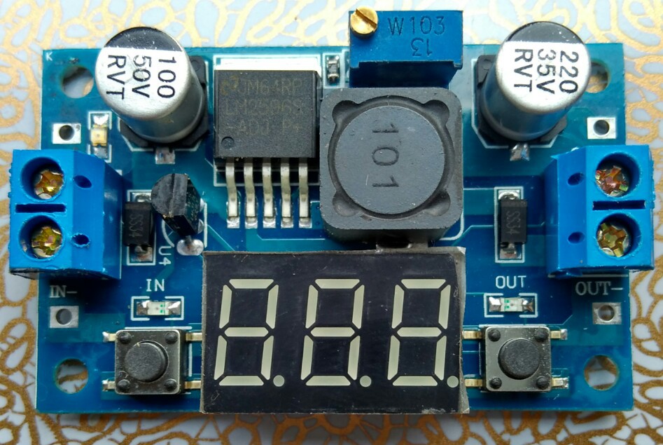
The first obvious thing, already visible on the vendor's pictures, is that the 7S-LED display nicely covers the voltmeter part including all the passive components.
Underneath the LED display we find this nice arrangement:
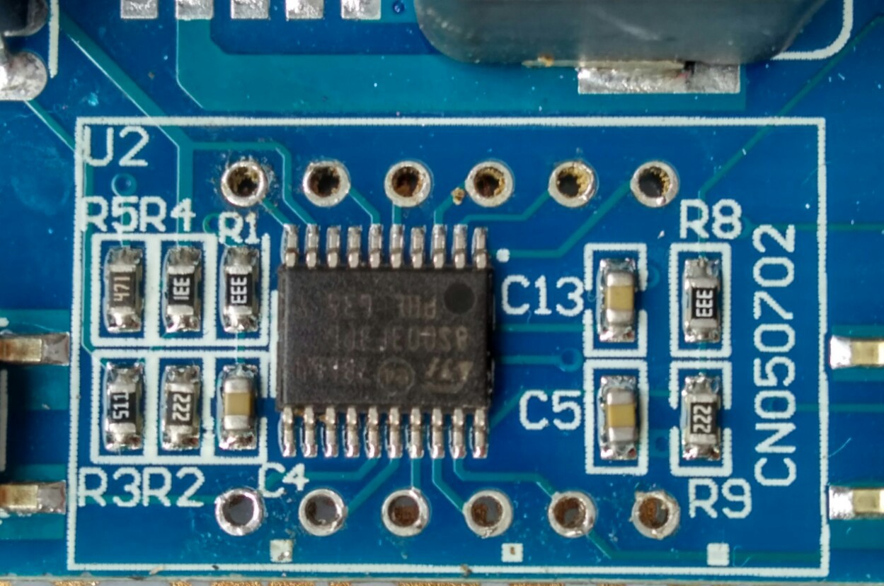
The LM317 in TO92 package is directly connected to the voltage divider R4/R3 (the LM317 lacks the recommended capacitor Cout, Cin is shared with the LM2596). C13 is connected to Vcap (STM8 1.8V core supply circuit). R1/R2-C4 and R8/R9-C5 are the "voltmeter inputs" (PC4 Vin, and PD3 Vout).
PC3 is connected to LED "in", and PB4 to LED "out" without current limiting resistor (the same as the 7S-LED display). Like in the first variant, the "design" relies on the limited current driving capability, and on the surprising robustness of the STM8S outputs. The LED power dissipation is limited by a 4% duty cycle (there is a risk of accelerated degradation). R5 is connected to the green power LED.
Isn't there anything else missing? Yes, a bypass capacitor for the STM8S003F3P6 - there is none!
So, if you ever had any doubt about the robustness of the STM8S: it's unfounded. It will tolerate circuit bending practices on a mass production scale ;-)
I first assumed that the GPIOs used for the 7S-LED display are the same but they're not since the STM8S003F3P6 is rotated by 90º with respect to the first variant.
Although the LEDs "in" and "out" are now connected to dedicated GPIOs, the keys are still connected to segment LED outputs (PC5/SegE and PD2/SegG), this means that the display should be blanked during a key-press. It would have been really easy to use PB5 for reading the keys but it was left unconnected.
As mentioned in my last post there is a thing I learned about the STM8 ICP interface: it will work without the NRST pin if SWIM hasn't been disabled in software or in the configuration bits. This means that one can get Forth onto it without soldering (PD1/SIM is connected to Pin4 of the LED display)! It will only work one out of three times, but that's OK for our needs, and once we have a Forth console we don't need the NRST anymore.
Now, what can we do with it this knowledge?
- for reading ADC values of any accuracy all LEDs should be switched off
- Vin is easily accessible on the backside of the PCB, and after cutting the trace it can be used for measuring anything else
- PC3 can be exposed by removing LED "in" (there is no resistor!)
- LM2596 Pin 5 "/ON-OFF" can be cut and connected to PB4 for controlling power out (even without removing LED "out")
- PB4/ can be exposed by removing LED "out"
- for controlling the LM2596 feedback loop the pot wiper can be connected to GPIO PC3
- The Vout ADC can be used for closing an output voltage (or current) control loop
Controlling a DC motor or a hydraulic valve solenoid with this variant of the "DC/DC converter with voltmeter" module appears to be very feasible.
Other applications might be:
- Precision temperature control (i.e. not switching-mode but by setting the power!)
- Low-grade lab power supply with some control features (scripting, monitoring, synchronization, maybe even fold-back current limiting)
- LED power supply with current control
- battery charging
- ..
Who said that a piece of electronics with a horrible design can't be turned into something useful? I hereby put this $1.52 gadget on "strong buy" ;-)
I don't plan to support the first variant of the board as it lacks LED GPIOs that can be easily repurposed. So, if you want to buy one, better make sure to get this second variant (not the one in the first post). On AliExpress search for "LM2596 DC 4.0-40 to 1.3-37V Adjustable Step-Down". I've seen a green and a blue variant, and both are easy to identify (LM317 as TO92, many passive components hidden under the 7S-LED display).
Edit1: some corrections on the circuit, and more details on the used GPIOs
Edit2: I've got the main parts of the board working. The GPIO initialization code in boardcore.inc is as follows:
        ; DCDC STM8S003F3 init GPIO
        ; Codes: A ... G+P - LED segments+DP,
        ;        1 ... 3 LED digits,
        ;        i ... o: LEDs "in", out,
        ;        ".": analog inputs
        ;        u: unused
        MOV     PA_DDR,#0b00001110 ; ----3AF-
        MOV     PA_CR1,#0b00001110
        MOV     PB_DDR,#0b00010000 ; --uo---- PB4:LEDout
        MOV     PB_CR1,#0b00010000
        MOV     PC_DDR,#0b11101000 ; PDE.i--- PC3:LEDin PC4:Vin PC5:E/keyIn
        MOV     PC_CR1,#0b11101000
        MOV     PD_DDR,#0b01110110 ; -21B.GC- PD2:G/keyOut PD3:Vout
MOV PD_CR1,#0b01110110Edit3: more corrections, some more details. I pondered how to best control the LM2596. My idea is to synchronize Timer1 with the LM2596 switching oscillator, and to use the PC3 PWM duty cycle to control the feedback loop. It can't be much worse than the B3603.
Discussions
Become a Hackaday.io Member
Create an account to leave a comment. Already have an account? Log In.
Great job ! what do you think about the variants with single button and two leds ? would it be possible to add extra ground sense amp and a feedback loop for constant current drive with the same chip.
Are you sure? yes | no
Hacking the LM2596 has some limitations, but hey, why not try something new? The I/O capabilities of an STM8S103 that also drives an LED are a bit limited, of course. If the layout of the boards is still the same, LED_OUT should be PD2/AIN3.
https://hackaday.io/project/19647/log/173501-new-boards-have-arrived
Are you sure? yes | no
Yes it very much resembles the one in your post though with a slight differences, you may take a look at the images in the link below. I haven't desoldered the 7-segment display yet but from side view it is pretty much the same. The board lacks decoupling capacitors of stm8 but also the caps for the low pass filters of analog inputs as well. One thing i dont understand how stm8 samples the voltage, i mean there seems like a voltage divider network 33K / 22K, but theroratically the maximum analog input voltage in this configuration is maximum 22K/(33K+22K)*1.8V(VDD) = 4.5Volts right ? for some reason when i probe the voltage in between these resistors, it doesn't seems to change along with the change of Vin or Vout.
(https://www.ciceksepeti.com/voltmetreli-lm2596-ayarlanabilir-3a-guc-kaynagi-voltaj-dusurur-kcm43212472).
Are you sure? yes | no
I've been off-line for a week - sorry for the late reply :-)
The "Low density" parts all use the supply voltage as the analog reference (not the core voltage!). In my experience, the STM8 analog inputs show relatively little dependence on buffering capacitors (there is more noise but relatively little additional offset).
I've uploaded the KiCad files with the schematics so that you can document your DCDC-MH variant if you like!
https://hackaday.io/project/19647-low-cost-programmable-power-supply/files
Are you sure? yes | no