 David H. Bronke
So, I finally go around to transferring this from the breadboard to a protoboard with its own enclosure. Looks kinda hacky, but it works great!
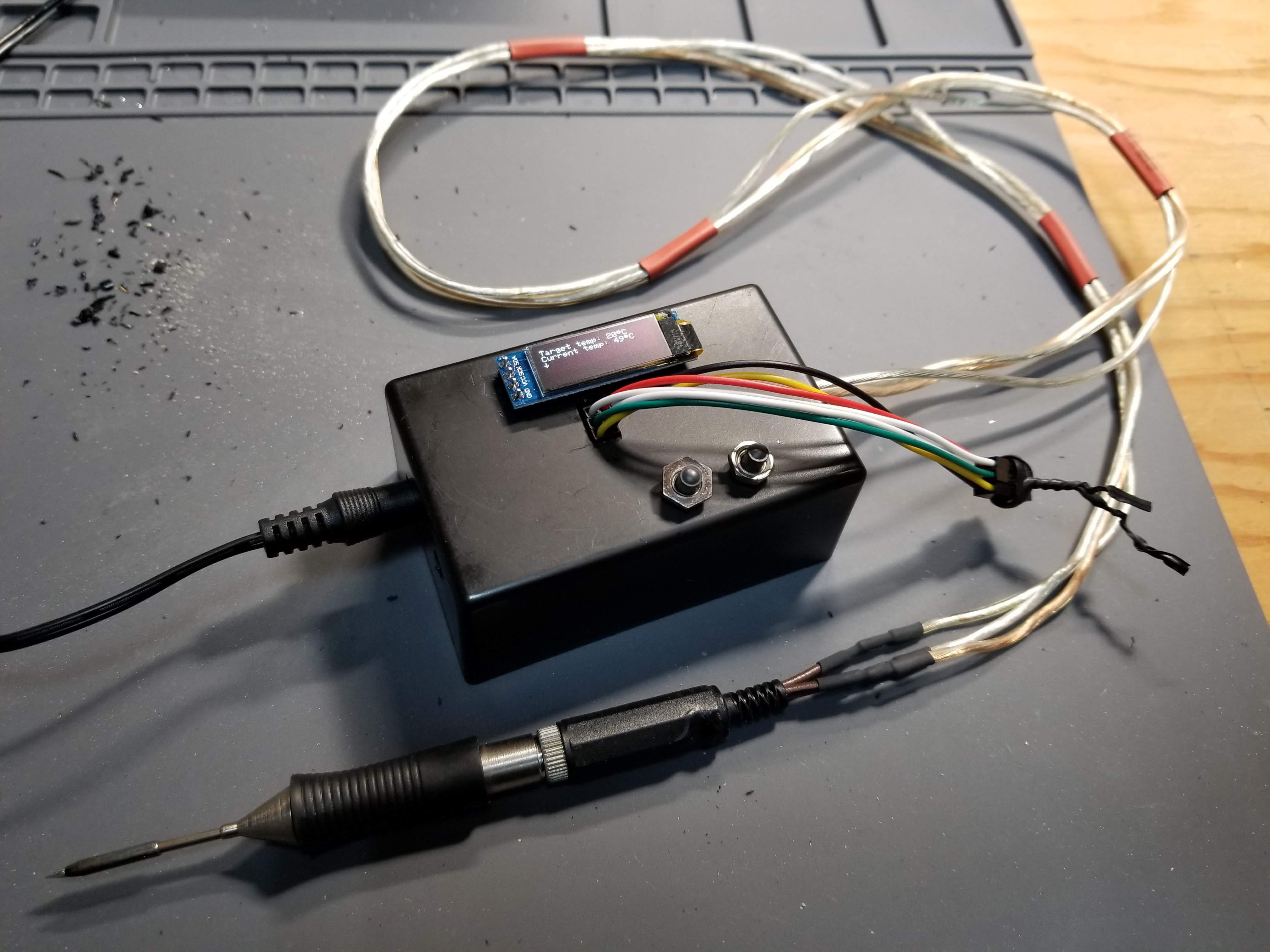
More glamour shots:
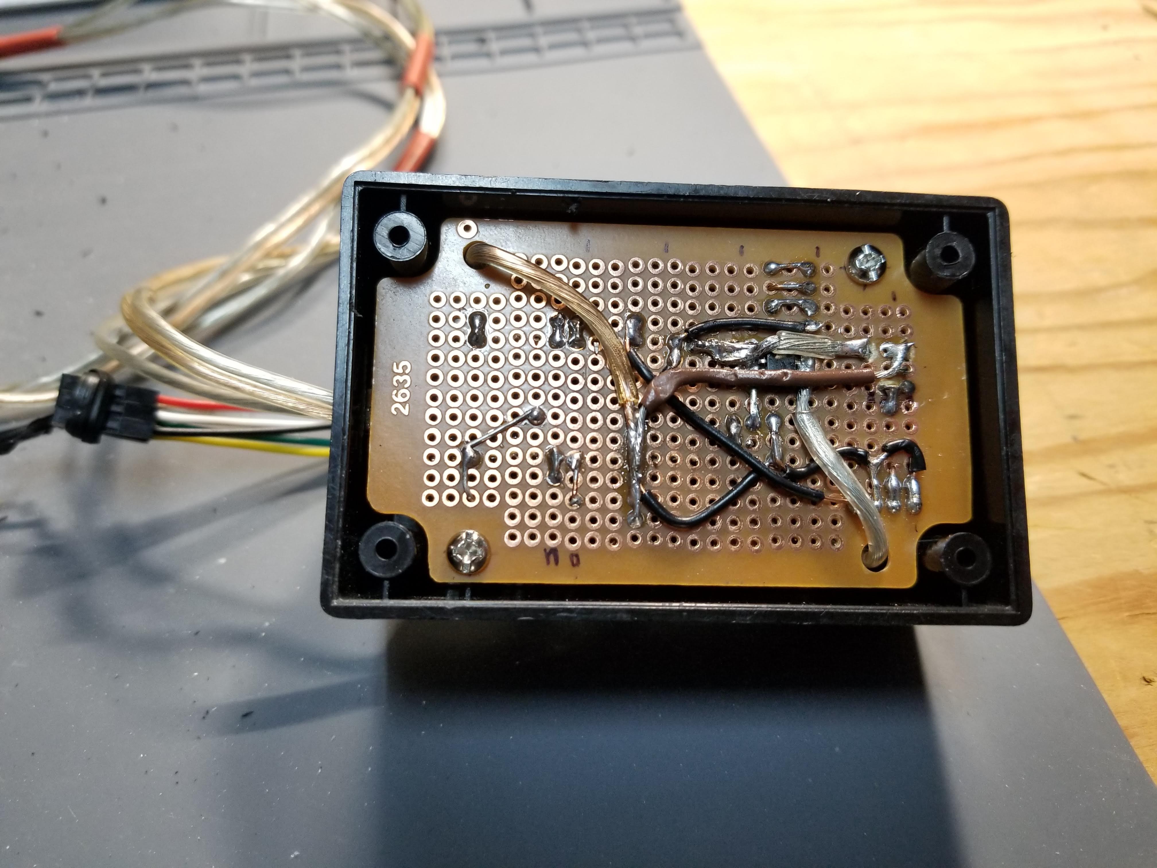
My wonderful solder job. Sadly, I had already crammed the whole thing into the box before I thought to take any photos. Also, I seem to have lost the cover for the project box, so it's currently open on the bottom.
Somehow, this thing actually worked the first time I plugged it in. I'm still shocked.
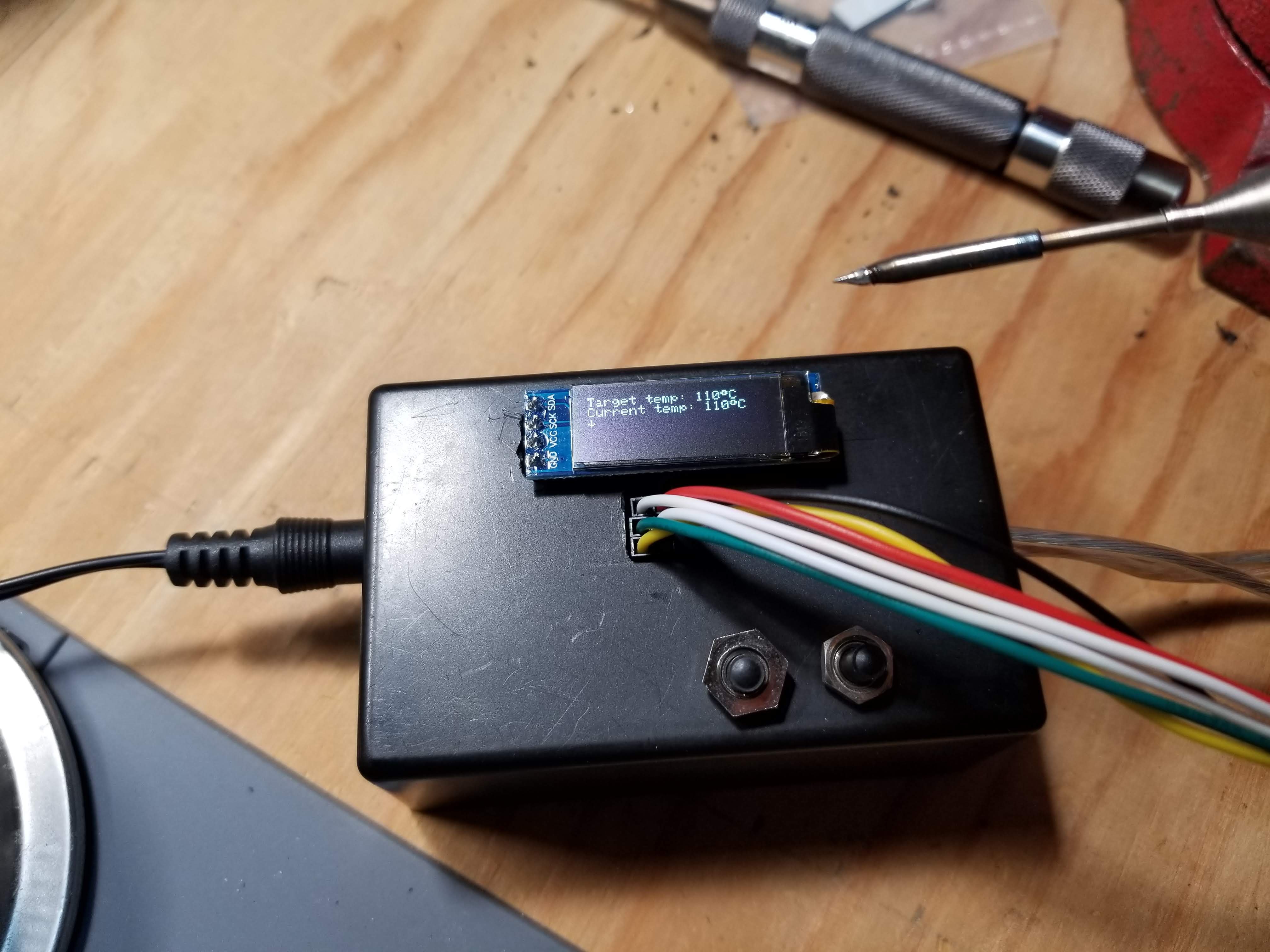
The temperature control is still about as accurate as it's ever been. (read: not very, but at least it's consistent)
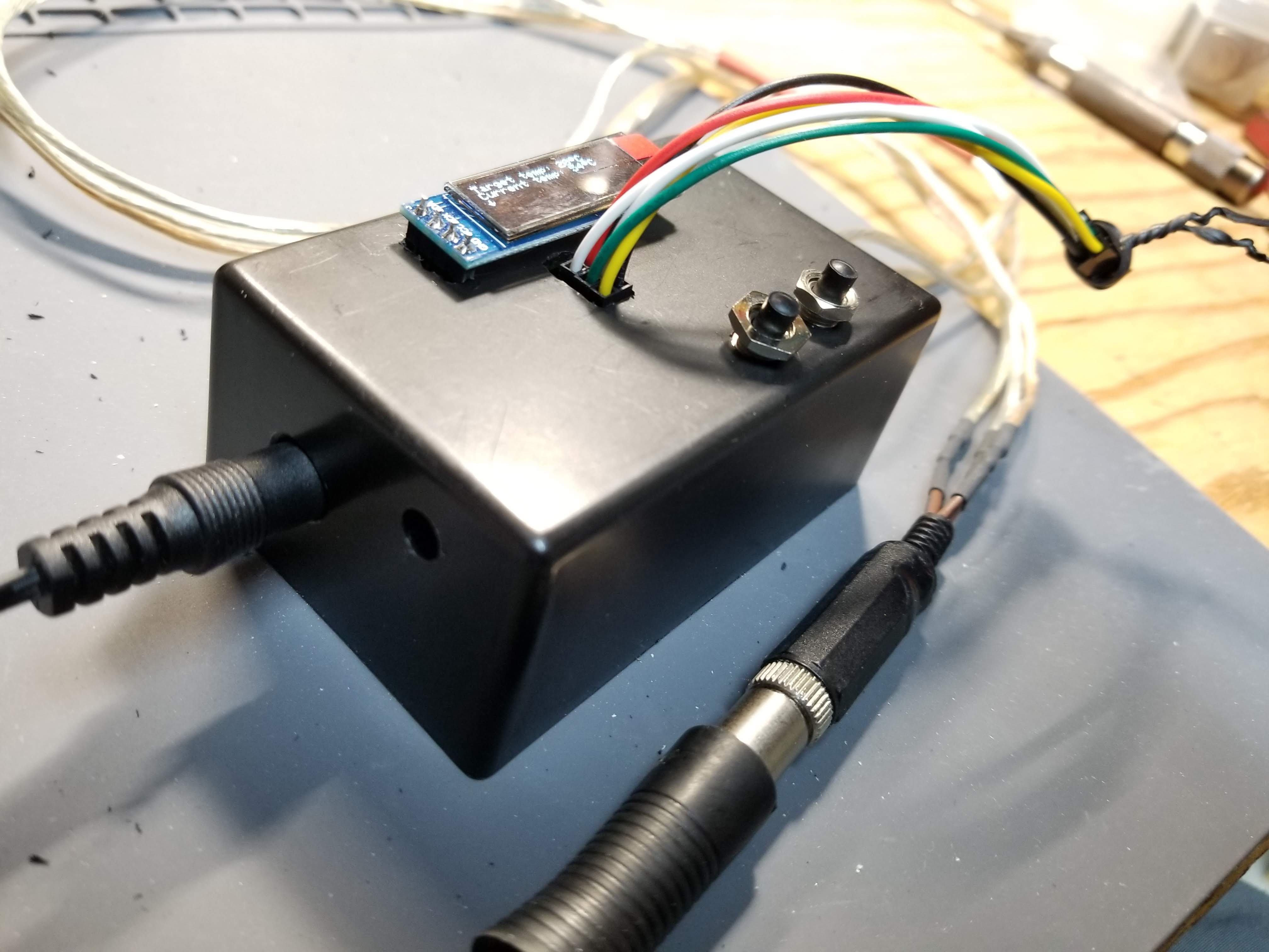
This would be a great marketing shot, if it weren't for my terrible case job.
- Those nuts are the wrong thread, so they're just cross-threaded on enough to stop the buttons from falling back into the box.
- The extra hole on the side was my first attempt at routing the ICSP header out of the box, but the connectors were too tall, so... now it just sort of hangs right out the front plate. Yes, that's a twist tie.
- The OLED of course had to be external to make things line up conveniently given the parts I had on hand. (I used an old wire-wrap IC socket plugged into a regular socket on the perfboard, and then plugged the OLED into the wire-wrap socket through a hole in the case)
- The old, melted stereo jack is back, because I accidentally melted my second nice red one too much while trying to solder it. This one at least works, and the tip doesn't just fall out of it.
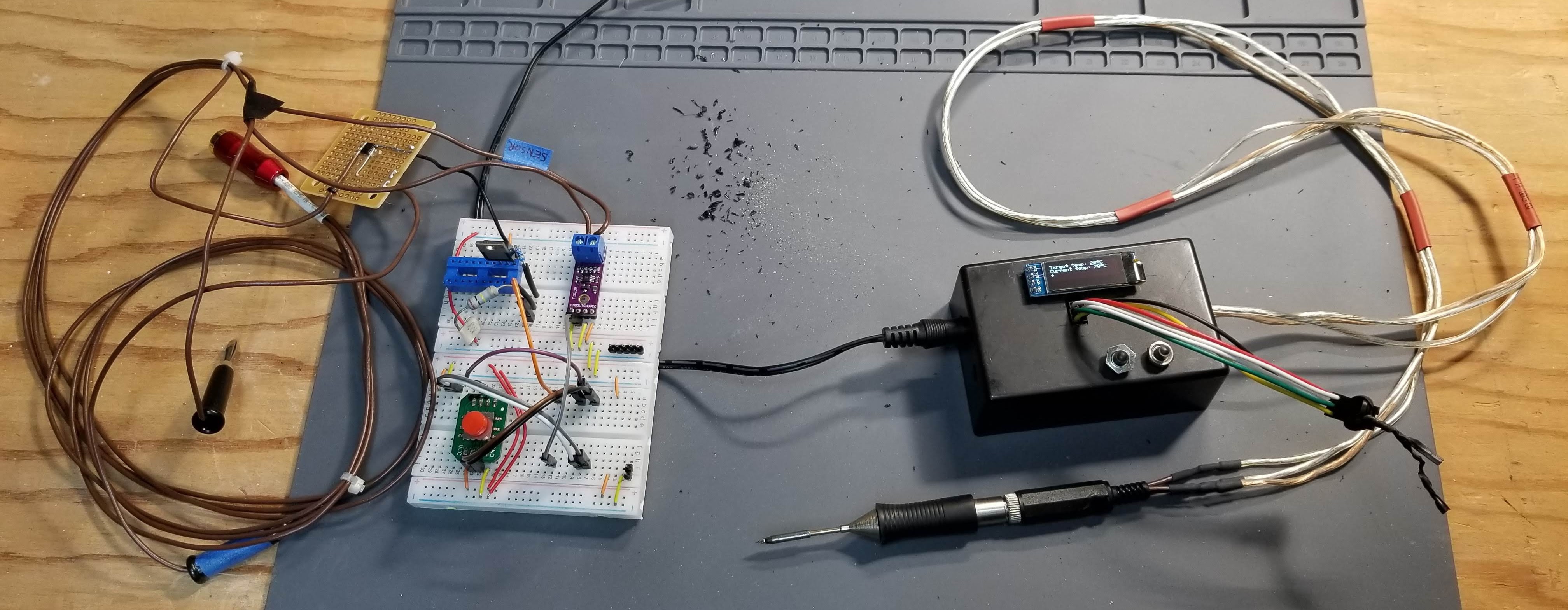
The old and new side-by-side. Here you can see that I've pulled some parts from the old one: the OLED and the Arduino Nano now live in the new box, and the rest of these parts will probably be pulled off the breadboard soon.
All in all, I'd say this project has been a success! I may pursue getting some actual boards printed professionally and maybe 3D-printing a custom enclosure, but for now I'm pretty happy that I managed to build my own soldering iron controller that works so much better than any of the other irons I own.
One more thing I'll probably change soon, though: I want to get some terminal blocks so the cord is completely removable without unsoldering or cutting wires. That way I can swap it out for a better cord once I find some 3-conductor stranded shielded cable and get a new stereo jack. Oh, and a power switch might be nice. Maybe I'll make use of that extra hole in the side?
Discussions
Become a Hackaday.io Member
Create an account to leave a comment. Already have an account? Log In.