David H. Bronke
-
GitLab project; Op-amps
09/15/2018 at 14:46 • 0 commentsI just added a link to the new project on GitLab! Now everyone else can actually access the code and the Fritzing sketch for this project.
In other news, I'm still trying to figure out if one of the OPA4228PA I have on hand will suffice for reading the temperature sensor in the RT tip, or if I need to wait for the OPA344 that was used in @banjohat's project... The OPA4228PA isn't rail-to-rail, but it is "high precision, low noise". I'm going to try breadboarding it and see if I can get it to give me useful results.
Also, I realized that the common anodes on the LED display will actually each need a transistor to drive them, possibly paired with a resistor to limit the current. That makes things significantly more complicated, since it only seems to work if I use PNP transistors, and I only have 2 of them that actually do anything in the circuit right now. Looking at the possibility of a Darlington array chip (and maybe also a resistor array) to keep component count down.
-
Testing!
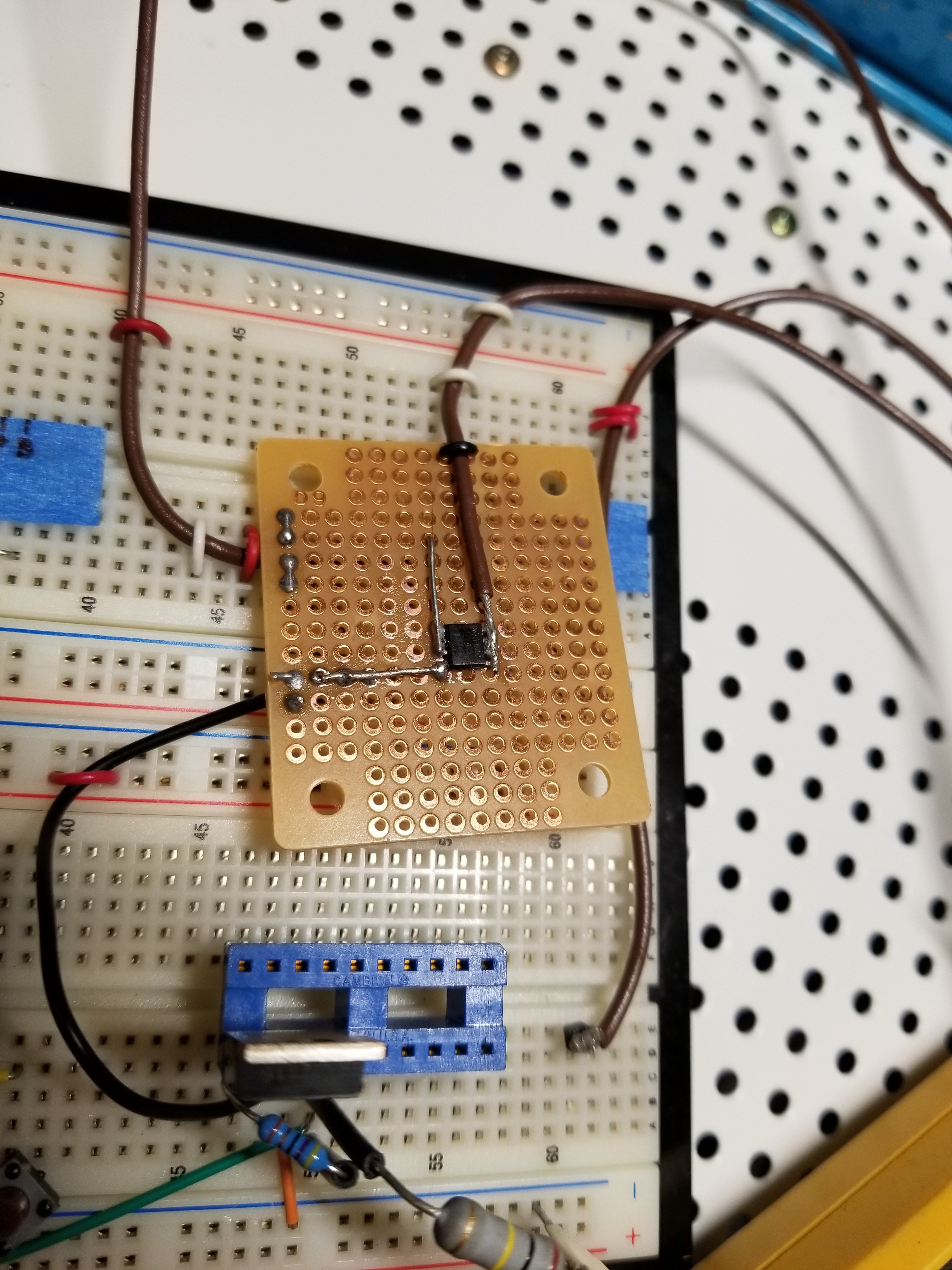
09/14/2018 at 16:56 • 0 commentsI've now put together the driver for the heating element in the soldering iron, and started testing. Here's a close-up of the second stage of the driver (soldered to cheap perfboard because this MOSFET is in an SO-8 package):
![]()
Hand-soldering SO-8 to a breadboard with a cheap Velleman iron: fun! Note that the first version of this was just leads soldered to one of the chips, but on that one, the gate pin ended up breaking off, despite some attempted strain relief. I should really have known better.
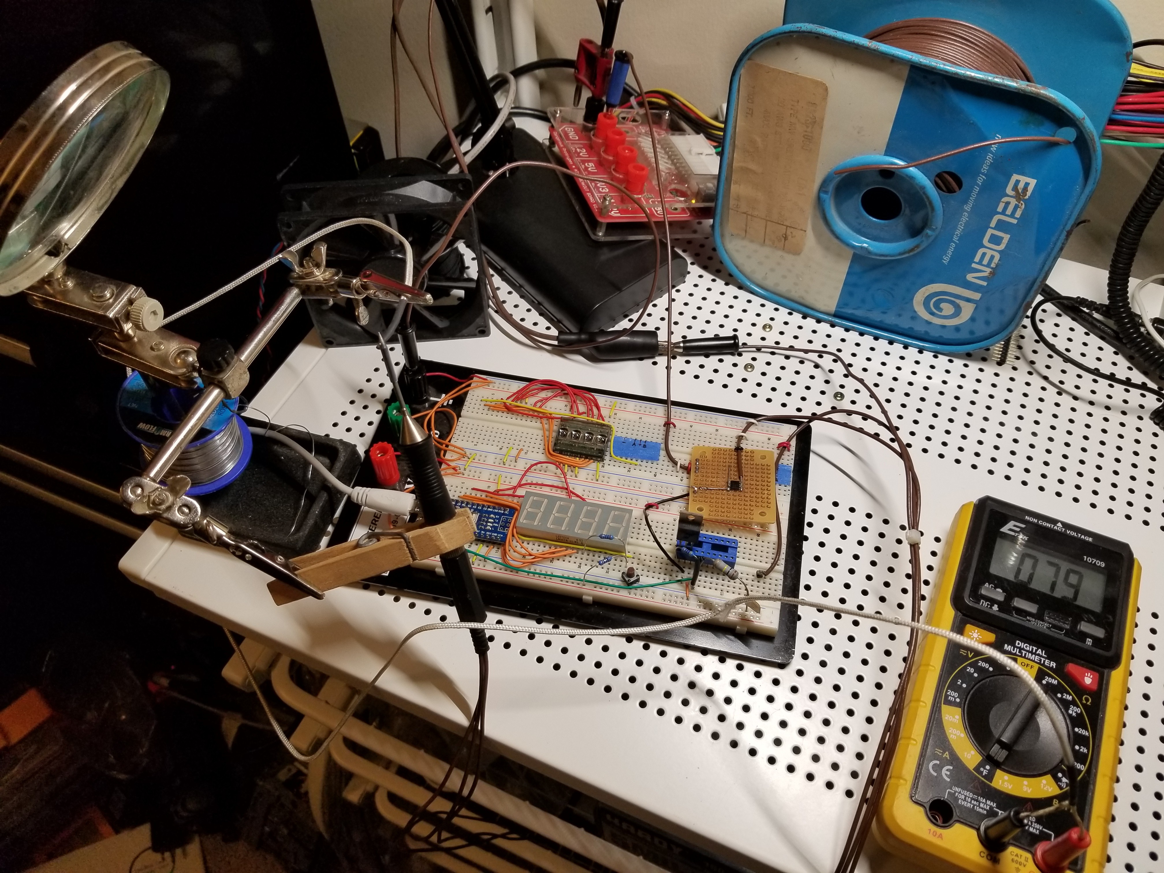
Next, I plugged everything in, and set up the soldering iron tip with a thermocouple touching it so I can check the temperature as it heats:
![]()
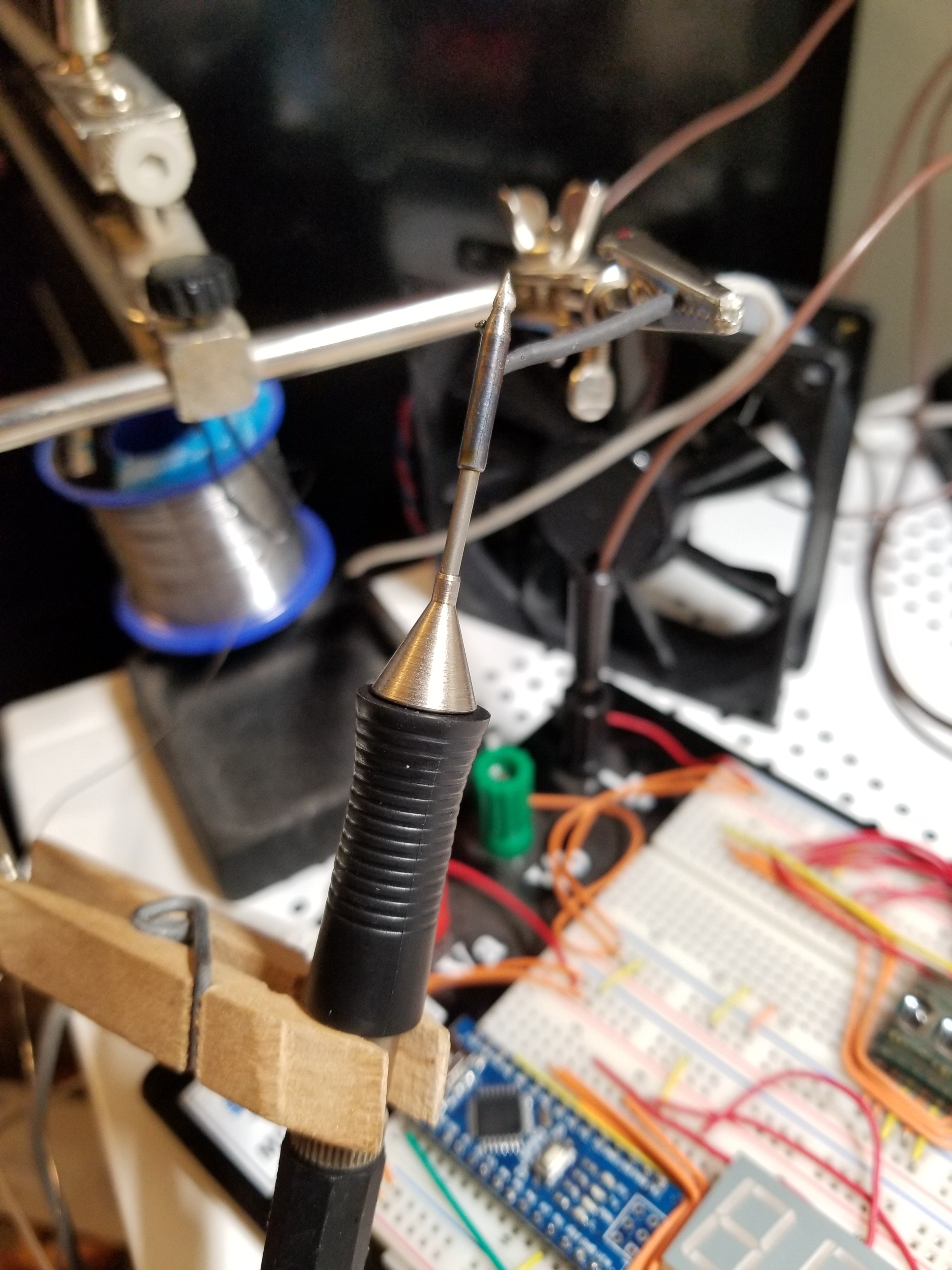
Look at how nice and clean that tip is! Well... it didn't stay that way for long. I made the mistake of actually following the schematic and connecting the iron supply to 12V... and I wasn't able to disconnect it quickly enough when it started heating like crazy, so it ended up getting up to around 500 degrees Fahrenheit. This oxidized the tip, though I was able to fix that with some flux and re-tinning... but the rest of the tip piece is now nicely blued:
![]()
The tip got a bit toasty. Good news, though: I didn't burn out the tip or any of the components! (though some smoke did emanate from the headphone jack, and it looks like the insulator in it has melted some... I might have to see about replacing that with a jack that makes a better connection)
I've been able to test out heating using different duty cycles (so far I'm using a 200ms period, though I may increase that) and it seems that the iron actually heats pretty quickly even on 5V instead of 12V. (though I'll need to check whether or not I can actually pull 2.63A from the Arduino's supply pins... I get the feeling that might not be feasible, which will mean I'll need to use something other than USB for the 5V supply) It even works OK on 3.3V, but doesn't actually heat very quickly. (though, to be fair, I've only tried that with up to a 15% duty cycle, so it may still give somewhat passable results if I try a higher duty cycle... and at 3.3V the heater will only draw 1.74A)
Next step will be to get the temperature sensor hooked up so I can start building a model based on my thermocouple readings... and then, on to PID control!
Also, since the heater switching causes my power supply to click audibly, I should probably figure out how to filter the transients out of the supply rails before trying to run this thing entirely off USB.
-
Arduino and different LED display
09/13/2018 at 20:30 • 0 commentsI've been having issues getting the PIC to do anything. I tried a bunch of different things, even attempting to just make an LED blink, and... nothing.
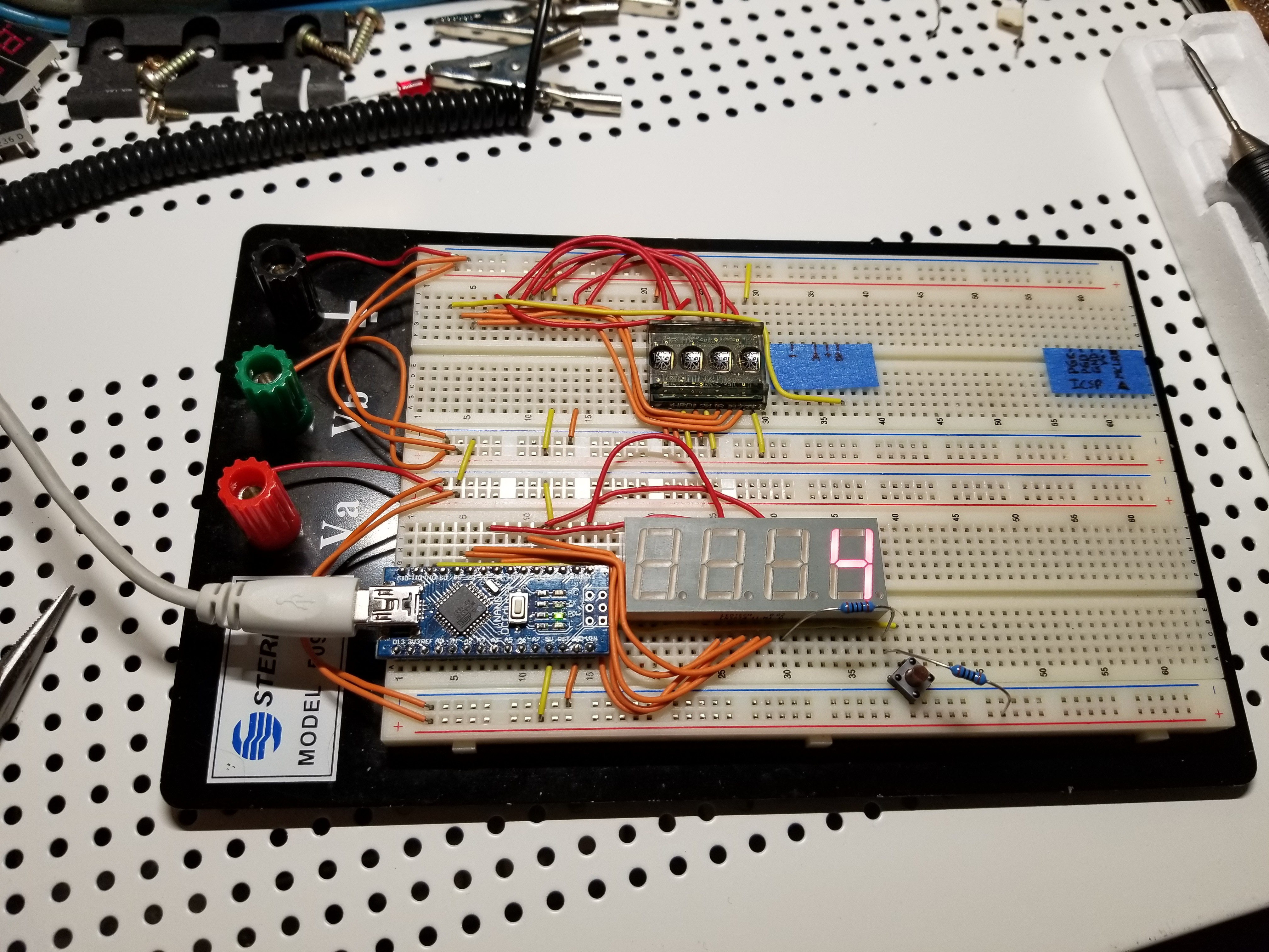
So, last night I realized I had an Arduino Nano clone sitting around, and I decided to give that a shot instead. Works great! But I still couldn't get the HPDL2416 (the LED display) to actually display anything, so now I've switched to a different one I had bought a while back. (a LEDtech LN5674-11-M1) Now I actually have it displaying one digit that counts up from 0 to 9 and then loops!
![]()
Next step will be to make it display a full 4-digit number (or maybe 3-digit with "C"/"F" after it), and then hook up the encoder... which reminds me: apparently my rotary encoder is also broken - it only gives me a signal out of one of the A/B pins. So I may have to wait for the new one to come in.
I wonder what happened to break all my components... maybe moving across the country, and then moving again a year later.
-
PIC code
09/12/2018 at 17:24 • 0 commentsI've put together the schematic and breadboard layout in Fritzing (I'll be uploading the files soon) and put together the first part of the circuit on my breadboard - the PIC, display, rotary encoder, ICSP header, and Mode button. Now, to program the PIC so I can test this stuff out...
And now I'm starting to realize why AVR/Arduino has been replacing PIC as the darling of hobbyists in recent years. PIC's architecture is... peculiar. The few open source tools that support PIC programming aren't updated like they used to be. (PikLab no longer builds on my system, for instance, and SDCC's PIC support is still experimental) There's very little library code available from the community. (it looks like I'm going to have to code my own PID controller) AVR, on the other hand, is quite well supported by open source tools, and has an active community contributing reusable code for it.
In short... if I actually had some AVRs on hand, I'd probably use them instead of the PIC. But since I don't... on with the coding.
-
PIC choice
09/08/2018 at 12:15 • 0 commentsI've already soldered together the jack for plugging in the RT tip, but now I need to figure out which PIC to use... so I'm going to use this post to catalog what pins I'll need.
Inputs:
- 1 analog - temperature sensor (via op-amp)
- 2 digital - for rotary encoder
- 1 digital - for standby switch (possibly not used until I get a better 3.5mm jack that actually supports this, unless I decide to pull the trick where I check if the tip has connectivity to the stand)
Outputs:
- 1 digital - heater control (to MOSFETs)
- 7 digital - display (using the HPDL2416: 1 write pin, 2 address pins, and 7 data pins, though 3 of the data pins can be driven by 1 pic pin with an inverter)
I'm still undecided as to whether or not I want to expose the ICSP pins, since my plan is to use a DIP socket, and I have a separate programmer socket I can use to program the PIC. On the other hand, it may be much more convenient to be able to simply connect the programmer to the soldering station directly.
Total I/O pins: 12 (or, with ICSP, 15)
Given the above pin lists, we should be able to use a 20-pin PIC. I have a few of these available:
- PIC16F690 - I have two of these, and it's the chip I'm most familiar with.
- PIC18F1220 - I only have one of these
- (PIC24F04KL101 - This one apparently doesn't have any A/D pins, so it won't work, though I have a tube of 5)
Looks like I'm going with the PIC16F690 again. :)
I'd also like to understand the MOSFET output stage used by the Soldering pen project better - especially why one of the MOSFETs shown on the schematic there is N-channel and the other is P-channel. (even though only one part number is shown in the BOM) I've been reading up on using MOSFETs to control heaters, but I'm still not sure if any of the parts I have on hand will be sufficient to drive the tip, and I'm not entirely sure whether it's possible to build a correctly-working output stage using various mixes of P-channel and N-channel parts. (P/P vs. P/N vs. N/N) Luckily, none of this should affect the pin count, so it shouldn't influence the PIC choice directly.