Close
0%
0%

Kord Kontroller

The goal of our project is to design a musical interface which emphasizes common tonal relationships in Western music theory.

Similar projects worth following
The goal of our project is to design a musical interface which emphasizes common tonal relationships in Western music theory.

We believe the layout of instruments such as the piano and guitar do not intuitively emphasize the relationships used for building chords. Traditionally, building chords relies on a user’s understanding of music theory and an intuition of relative pitch. This creates a steep learning curve for beginner musicians in building common chords quickly.

Our controller is designed to accentuate patterns between tones in a way that helps the composer create chords and motivates them to make music.

Kord Kontroller 

The Kord Kontroller is a musical interface that maps common chordal relationships in Western music theory. The controller is laid out into two sections: the key selector area and tonal selector area. 

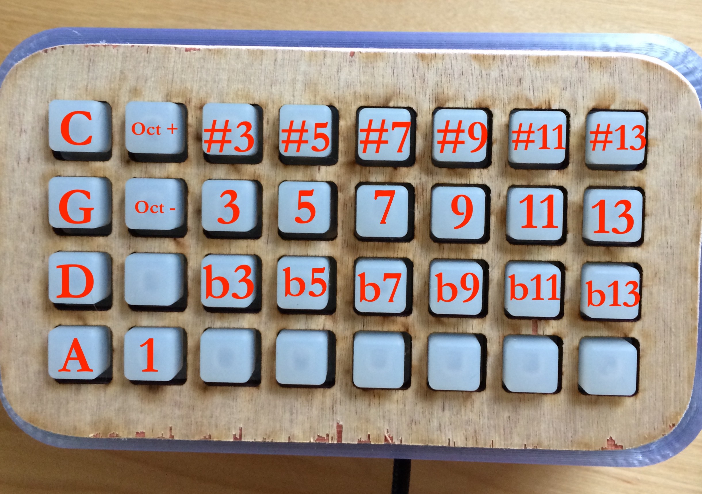
The three type of key selectors are a piano key selector, a circle of fifths key selector, and an isomorphic key selector. Once you select a note on the key selector, for example a C, this maps the tonal selectors in a consistent pattern regardless of the key. The tonal selectors are mapped to the 1 3 5 7 9 11 13 (C E G B D F A) of the key selected like below: 

   3  5  7  9  11  13

1  

The 1 (or the root) and these corresponding notes are selected because they are really common chordal relationships. The 1 is mapped topographically lower on the controller in order to match your hand lay out and since it is commonly played with your thumb. This allows you to play major chords and other common chords in the same pattern regardless of the key!

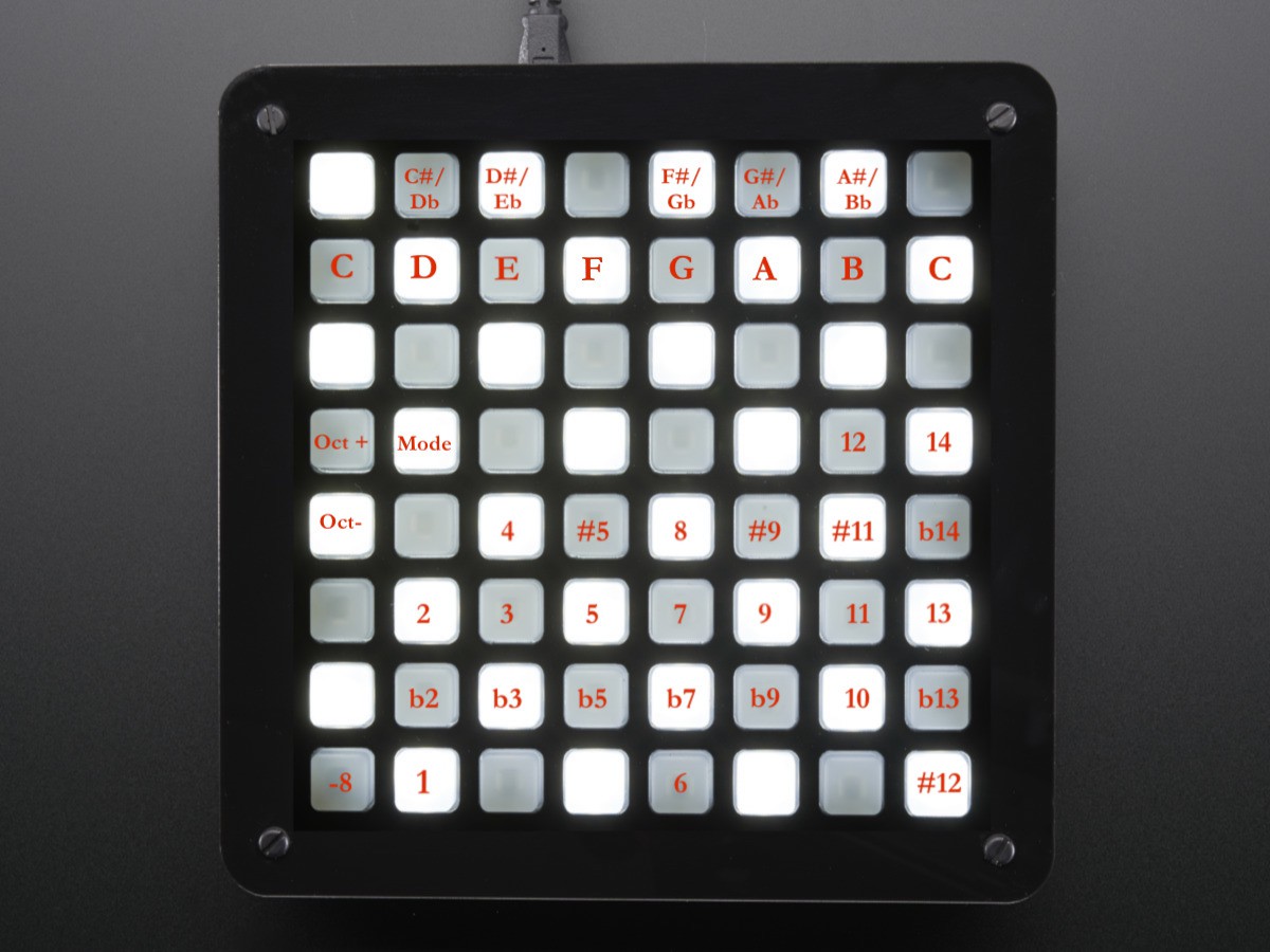
We did not want to only let you play major chords so we added the flat and sharp equivalent rows: b3 b5 b7 b9 b11 b13 and #3 #5 #7 #9 #11 #13. (Note: we understand that it is not common to refer to the 4 as a #3 or the 8 as #7, but this is more to emphasize the relationships). This allows one to play minor chords and other chords in the exact same way as well. We also added some other common notes like the 2 b2 12 14 etc. We also added octave buttons and mode changes to switch the key selectors. This ended up with this final layout: 

                                  12   14
         4  #5   8   #9  #11 b14

  2     3    5    7    9   11   13

 b2  b3  b5  b7  b9  10  b13

   1                6                #12


Next step is to build our own hardware so we can layout it out to our specifications. Let us know if you have any questions!
20180930_Trellis Button Layout.ods

This is a spreadsheet for the button indexes in the source code as well as the array indexes for the notes in the code.

spreadsheet - 14.68 kB - 10/07/2018 at 20:51

Download

20181007_KordKontroller.ino

This is the source code for the Kord Kontroller. See the Trellis Button Layout spreadsheet for info on how things are mapped in the switch-case statements.

ino - 39.09 kB - 10/07/2018 at 20:45

Download

Kord Kontroller Second Prototype_Testing Key Layout Modes.mp4

Testing the Layout Modes for the Second Prototype

MPEG-4 Video - 11.02 MB - 10/07/2018 at 19:55

Download

20180906_001537.mp4

Testing the First Prototype

MPEG-4 Video - 49.78 MB - 09/19/2018 at 02:11

Download

View all 6 components

  • Kord Kontroller - Walkthrough and Jam Sesh

    CSCircuits10/08/2018 at 01:21 0 comments

  • Second Prototype Build

    CSCircuits10/07/2018 at 19:52 0 comments

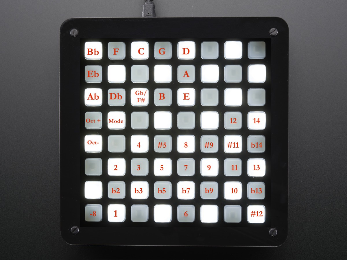
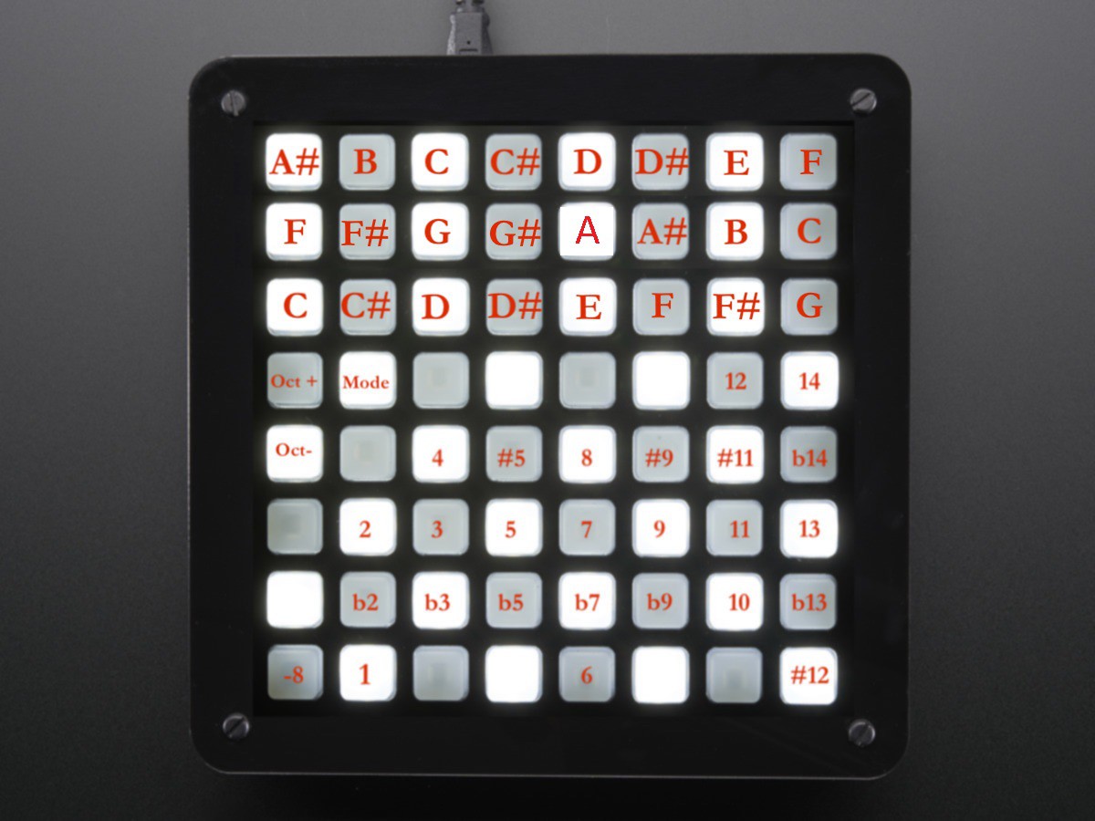
    For the second prototype, the goals were to add two more Adafruit Trellis modules to expand the button count to 64, place the prototype in an enclosure, and to write up code to test different layouts for selecting different music keys for the mapping of the notes on the controller.  The three layouts we wanted to test were a circle of fifths-style layout, an isomorphic layout, and a piano-style layout.

    Image 1. Circle of Fifths-Style Layout.

    Image 2. Isomorphic Layout.

    Image 3. Piano-Style Layout.

    As shown in images 1-3, the top portion of the controller changes with each layout while the bottom portion remains the same.  The top portion is the key selector for determining which notes the bottom buttons represent.  If the key of C is selected, note 1 is C, note 3 is E, note 5 is G, etc.  The button for selecting the key selector layout is the "Mode" button, and "Oct +" and "Oct -" raise and lower the octave for all the notes.

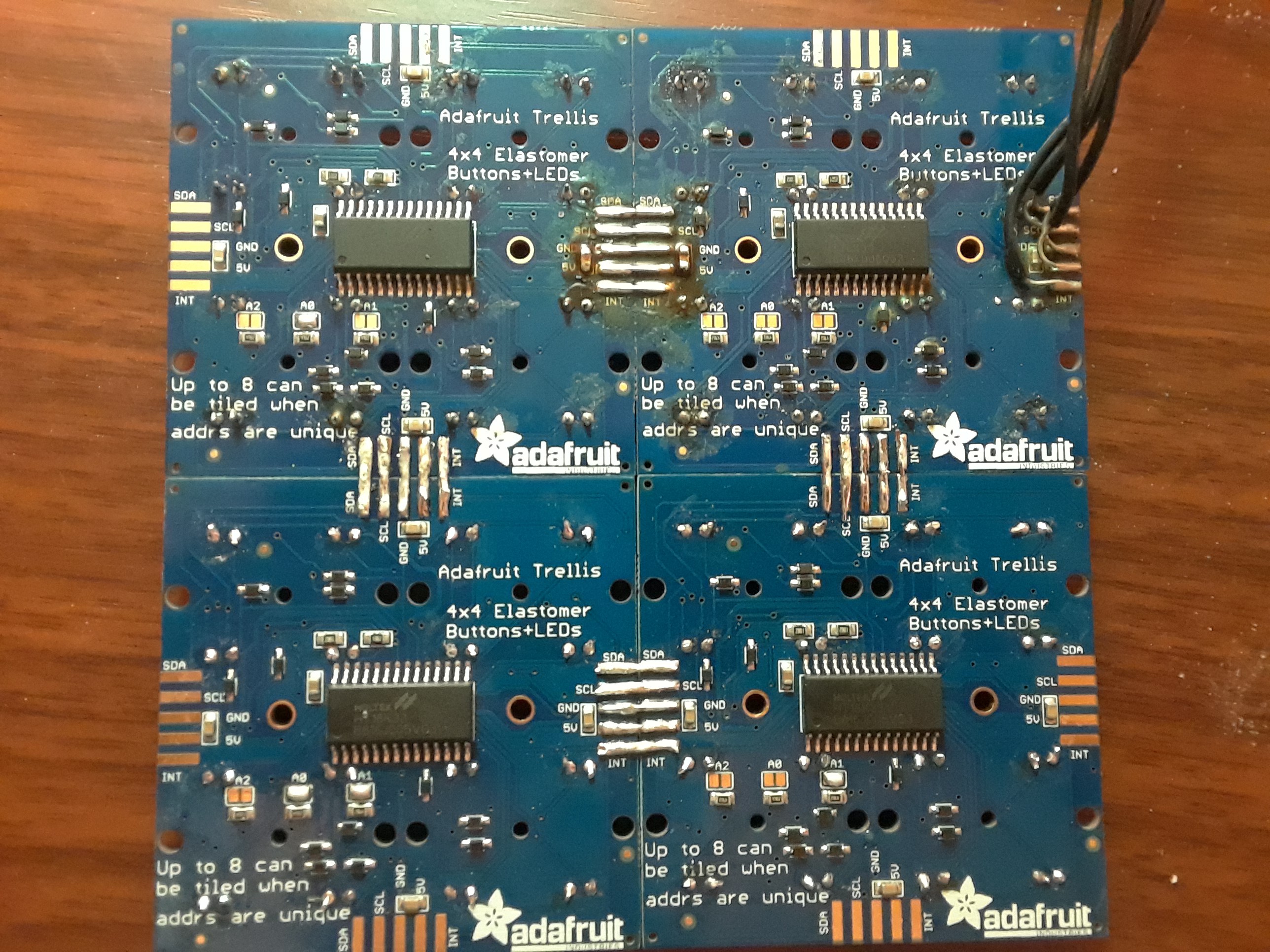
    The build began with soldering the Trellis modules together:

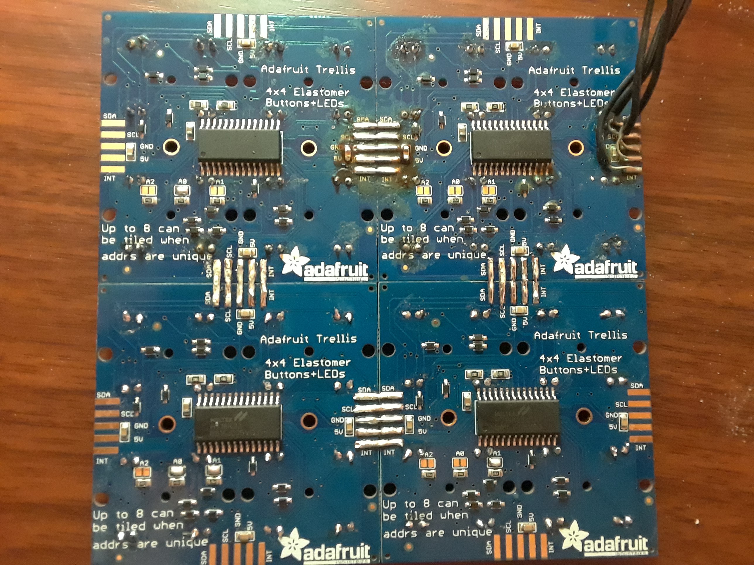
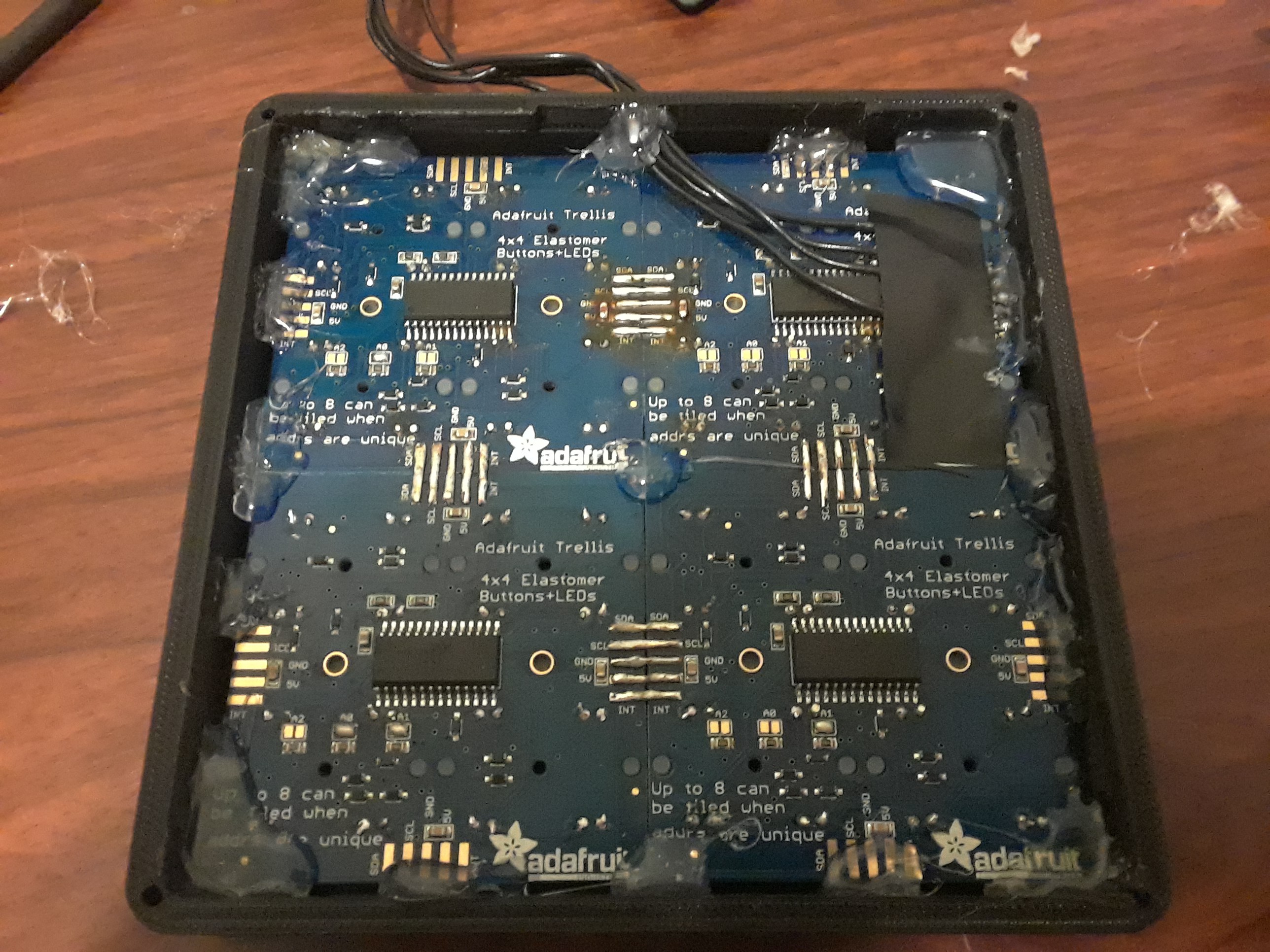
    Image 4. The 4 Adafruit Trellis Modules Soldered Together.  Copper wire was used to reinforce the connections between the modules.

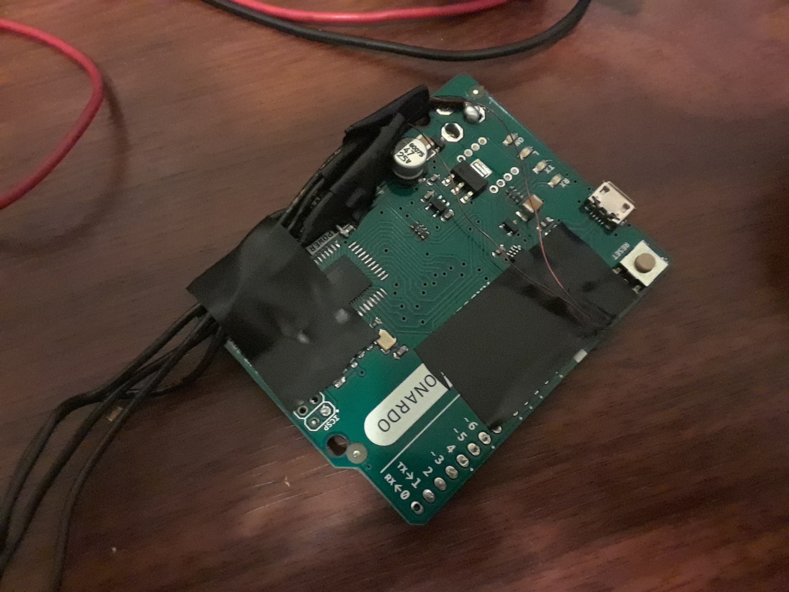
    In order to fit the Arduino Leonardo in the enclosure, the headers, the ISP connector, and the DC jack were removed.  However, disaster struck when all of the copper pads where the headers were soldered to the board lifted off.  In order to remedy this, the connections between the Trellis modules and the Arduino were made at different points on the board.  The +5VDC connection was made to a capacitor on the Arduino, the GND connection was made to one of the solder points where the DC jack used to be, and the SCL and SDA connections were made by scraping off some of the solder mask on the vias and using some magnet wire I had lying around.  So, much for a nice-looking Arduino board.  It was determined that it would be better to not try to squeeze the Arduino board into the enclosure because the spacing was very tight and it wasn't really necessary for a prototype.

    Image 5. The Salvaged Arduino Leonardo Board.  Isn't it beautiful?

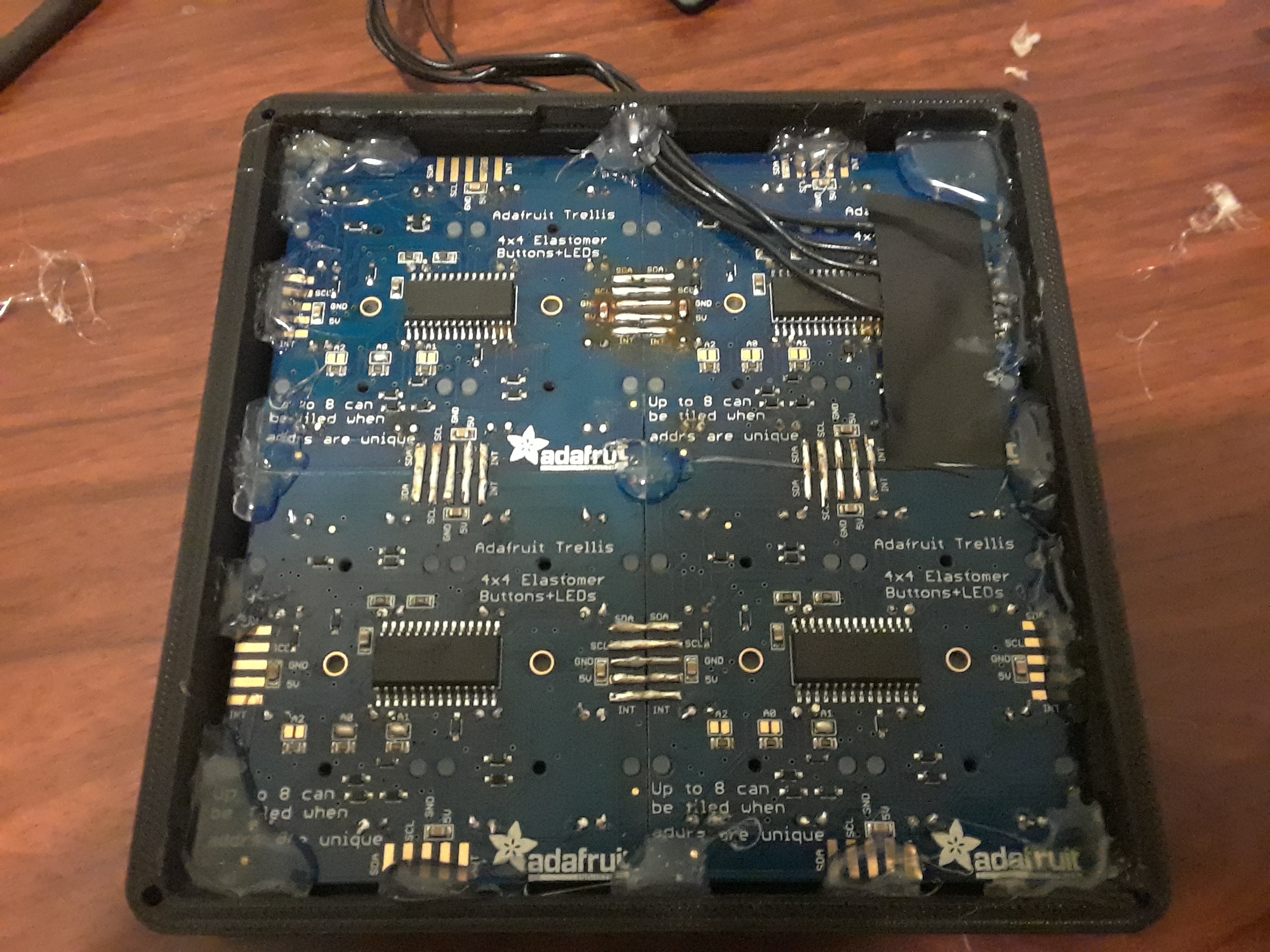
    Image 6. The Trellis Modules Hot-Glued to the Enclosure.  The hot glue ended up being sturdy enough for testing, but some additional support underneath the boards will be necessary for more extreme jam sessions.

    After battling with the hardware assembly, it was time to write up the code for the prototype.  The code will be uploaded shortly, but to summarize, I used the libraries released by Adafruit for indexing the buttons on the Trellis and for driving the LEDs.  The microcontroller constantly scans all of the buttons on the board and checks if a button was pressed or released.  The index of which button was pressed/released is used in a giant switch-case statement to determine the action for each button.  There are separate switch-case statements for each layout of the keys on a button press and a separate one for a button release.  The "Mode" button changes a variable that determines which switch-case statement to use.  With the way that MIDI works, a specific note is turned on by sending a pitch value to the PC (the velocity value for each note is set to max because this board does not have force sensing).  In order to turn a note off, the same pitch value must be sent to the PC.  So, I had to hold the current pitch value for each button in an array in the event that the user changes the note mapping while still holding down a button to play a note.  That way, it is guaranteed that the correct pitch value is sent to the PC to turn the note off when the user releases the button.  To determine the pitch value for each note, a formula is used based off the root note and the current octave.  Here is a link to a website that lists the MIDI pitch values for different notes in different octaves: https://musescore.org/en/plugin-development/note-pitch-values.  If the controller is set to...

    Read more »

  • Enclosure for Kord Kontroller Prototype

    MattD09/24/2018 at 01:51 0 comments

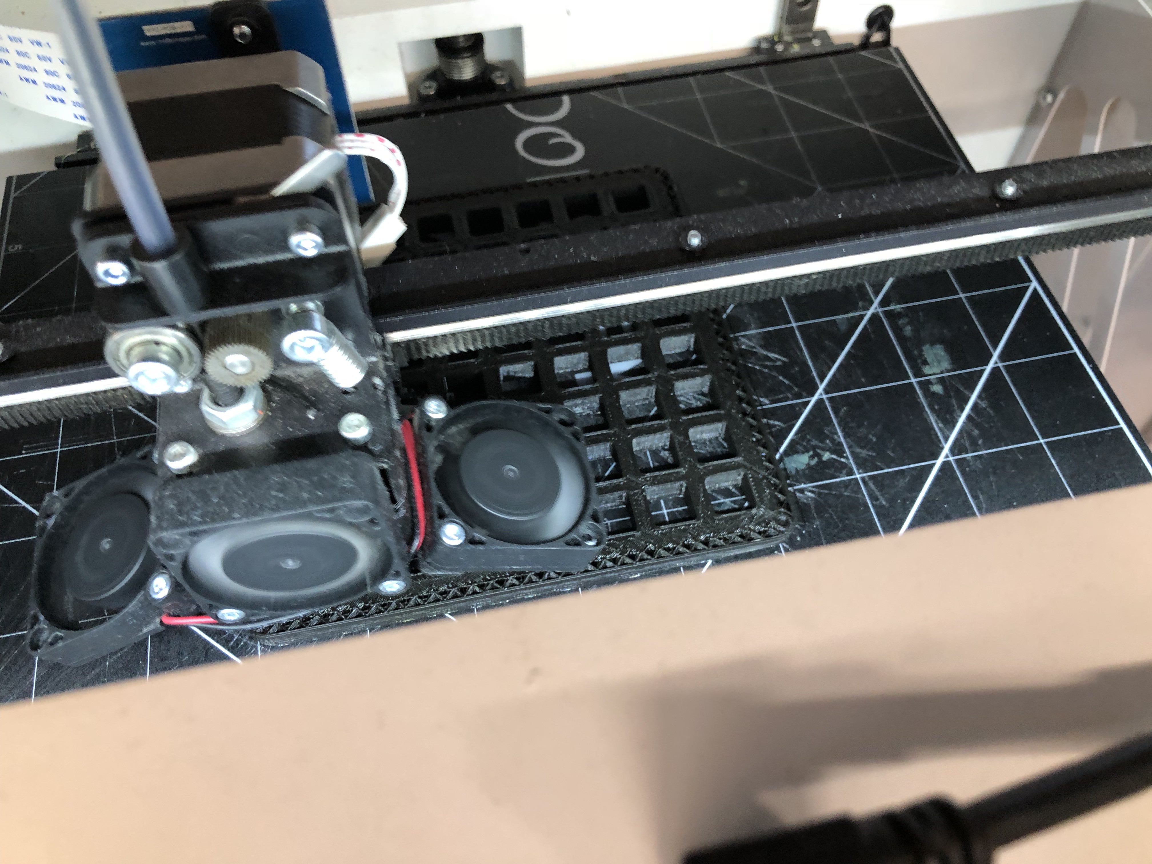
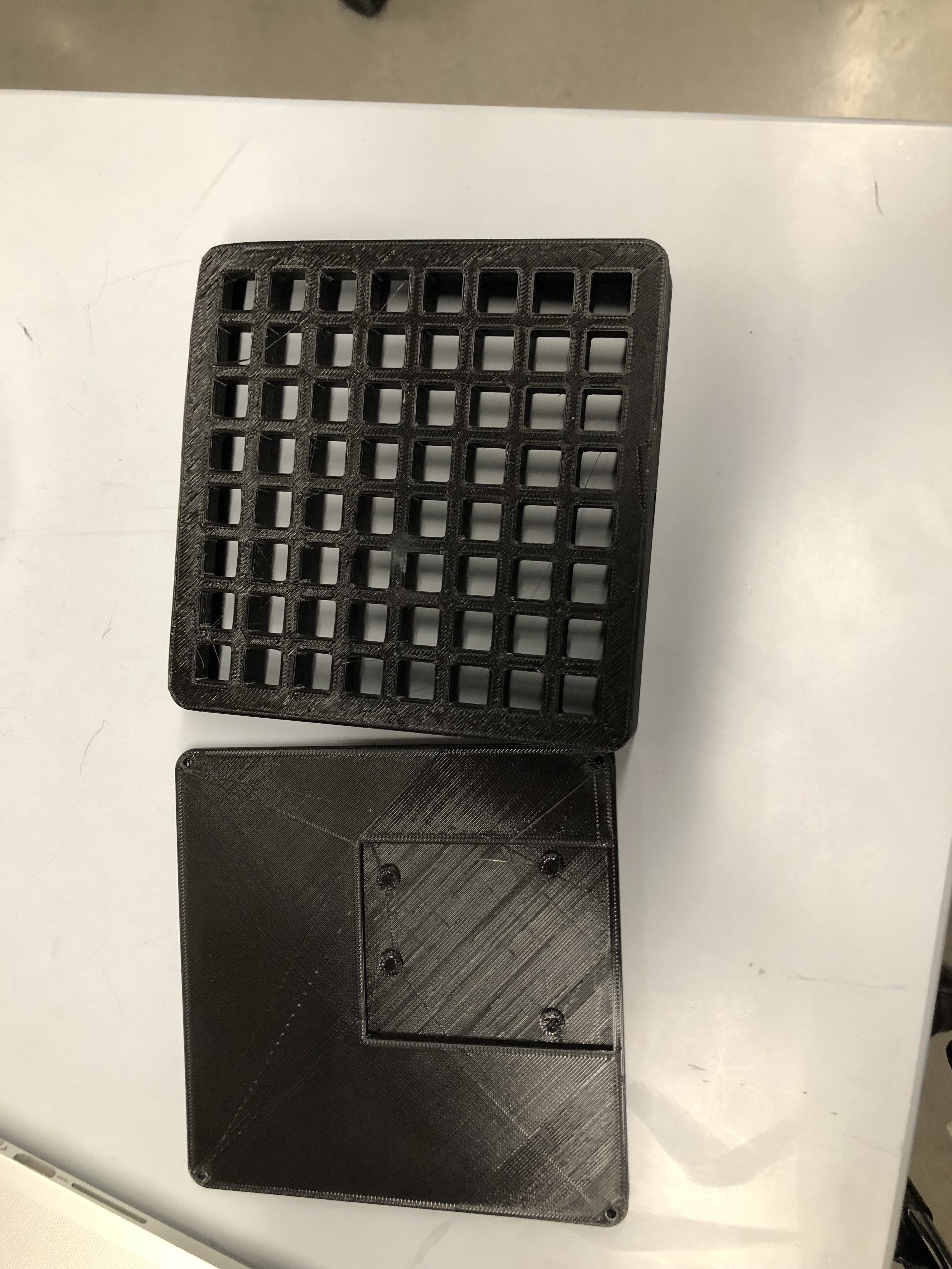
    Printed the enclosure on on a CraftboxXL at UT Maker Space. Over 6 hours print time! Shout out to Electronic_Grenade at Thingiverse for the 3D CAD file https://www.thingiverse.com/thing:2376245

  • Kord Kontroller: First Prototype

    CSCircuits09/24/2018 at 01:30 0 comments

  • Button Layout and Pizza

    eforzano09/16/2018 at 21:00 0 comments

    The Plight of the Chord

    The goal of our project is to design a musical interface which emphasizes common tonal relationships in western music theory. 

    Our team believes the layout of instruments such as the piano and guitar do not emphasize the relationships betweens tones used in building chords. Traditionally, building chords relies on a user’s understanding of music theory or intuition of relative pitch. This creates a learning curve for beginner musicians in building common chords quickly. 

    Creating a Solution

    Matt, Chase, and I came together to solve this problem. The interface we came up with is the Key Kontroller. The basis idea of the Key Kontroller is that you have a Key selection interface on one side and tone selectors on the other. Once a Key is selected (i.e. the key of C), all of the tone selectors are mapped out to common chordal tones of 1 3 5 7 9 11 13. For this example, it would map to C E G B D F A. This allows the user to have the same patterns for simple and complex chords. 

    Once the user gains the familiarity of this format is it almost encourages someone to want to play beyond the simple chords.  We wanted to instill the desire to explore and create rather than fear of playing the wrong note.  For our first key selector, we picked the Circle of Fifths as a starting point because of all of the musical relationships that can be realized in proximity of each tone and the added benefit of the compact factor in comparison to a piano layout. We are exploring other options such as the piano or a hexagonal grid pattern for a selector as well. This brought us to our first layout below. 


    However, we did not want to limit the user in what they could play. We did not want to make the mistake that a lot of controllers made in forcing someone to choose a scale. It limits the user in the notes they can play and forces the user to change scales in a live musical setting, which can be cumbersome and stressful. To solve this we added flat and sharp modifiers: b3 b5 b7 b9 b11 b13 and #3 #5 #7 #9 #11 #13. We also wanted to add the notes 2 4 6 10 12 14 with their flats and sharps.  We also added idea of an Octave Up, Octave down, and raised root (8) and lowered root (-8). This allows the ability to play melodies and have more freedom. Because sometimes playing the wrong note is the best note! This resulted in our second iteration. 

    Creating a Working Prototype

    After laying out what buttons we wanted, we needed to see if we were crazy and had to much pizza and beer. So we shredded up paper and tried to layout the buttons as a demo prototype. 

    The prototype seemed to feel comfortable, but we need to take it one step further. We decided to develop some code to see if this thing was playable. We set on using Adafruit's Trellis PCB due to it being open sourced, its light up buttons for feedback, and we knew we could already communicate with music software using MIDI. Because we only had 32 buttons with two trellis PCBs from a previous project. We decided to focus on 4 Key Selectors (C G D A), Octave Up and Octave Down, 1 (the Root), 3, 5, 7, 9 11, 13, and their flat and sharp equivalents. The one or the root was put at bottom corner to mimic the shape of your hand and allow your thumb to press the root easily like a piano chord. 

    We are excited to show you the next step in our project. Our next Build Log should be a video showing what we have developed so far. Feel free to post questions and comments below! 

View all 5 project logs

  • 1
    Assemble the Four Adafruit Trellis Modules

    Solder up the four Adafruit Trellis modules.  If desired, add LEDs to the top side of the board.  The orientation for the LEDs is noted on the silksreen on the top side of the board.  For more reinforcement, bridge the connections between the boards using some solid copper wire.  Also, solder some wire leads to the SDA, SCL, 5V, and GND connections.  The INT connection is not necessary for this build.  Make sure you jumper the A0, A1, and A2 connections to hard-code the index for each board.  The top right board is not jumpered, so it is board 1.  Top left has A0 jumpered, so it is board 2.  Bottom right has A1 jumpered.  Bottom left has A0 and A1 jumpered.  See the tutorial on Adafruit.com for more info on indexing the boards.  This directly correlates to the mapping in the source code!
  • 2
    3D Print the 8x8 Enclosure for the Trellis Modules
    Credit to Electronic Grenade from Thingiverse.  https://www.thingiverse.com/thing:2376245
  • 3
    Mount the Trellis Modules in the Enclosure

    Make sure to properly align the silicone buttons with the enclosure.  The buttons have dowels for aligning the PCBs.  Hot glue works perfectly fine for testing, but putting some support underneath the boards would surely help prolong the lifetime of the controller.  Route the leads out through the hole.  Hot glue can be used for strain relief on the leads.  Use M3 10mm screws for securing the backing plate.  To prevent the controller from sliding around the table, some rubber feet work great.

View all 5 instructions

Enjoy this project?

Share

Discussions

Similar Projects

Does this project spark your interest?

Become a member to follow this project and never miss any updates