Chris Miller
-
KiCad layout lessons
09/13/2018 at 04:18 • 0 commentsI learned something really important with KiCad today. Whatever you do, if the assign components dialog asks you if you want to annotate and renumber your components, do NOT do it if you've already routed the board. I thought it would renumber my components in both the schematic and layout with nice top to bottom numbers. Instead, I think it renumbered in the schematic only. So next time I updated my PCB layout from the schematic, all hell broke lose and components swapped locations and orientations all over the board. I'd saved while still in the schematic view, so there was no undo. It took about 2 hours to re-place around 100 components using the detached traces I'd been routing all day. Luckily the rough routing was done, and the highlight net tool cross-referenced with the schematic was very helpful.
![]()
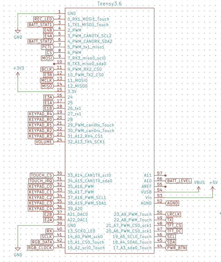
Do NOT select "reset existing annotations" if you've already done some routing. Unless you know what you're doing (which I didn't) On the bright side, I did get all of the functionality I wanted packed into the schematic and roughly routed. I managed to use all but ONE outside row pins on the Teensy 3.6. Tonight I'll test the pin assignments with my breadboard setup.
![]()
-
New Teensy 3.6, power and charging circuitry
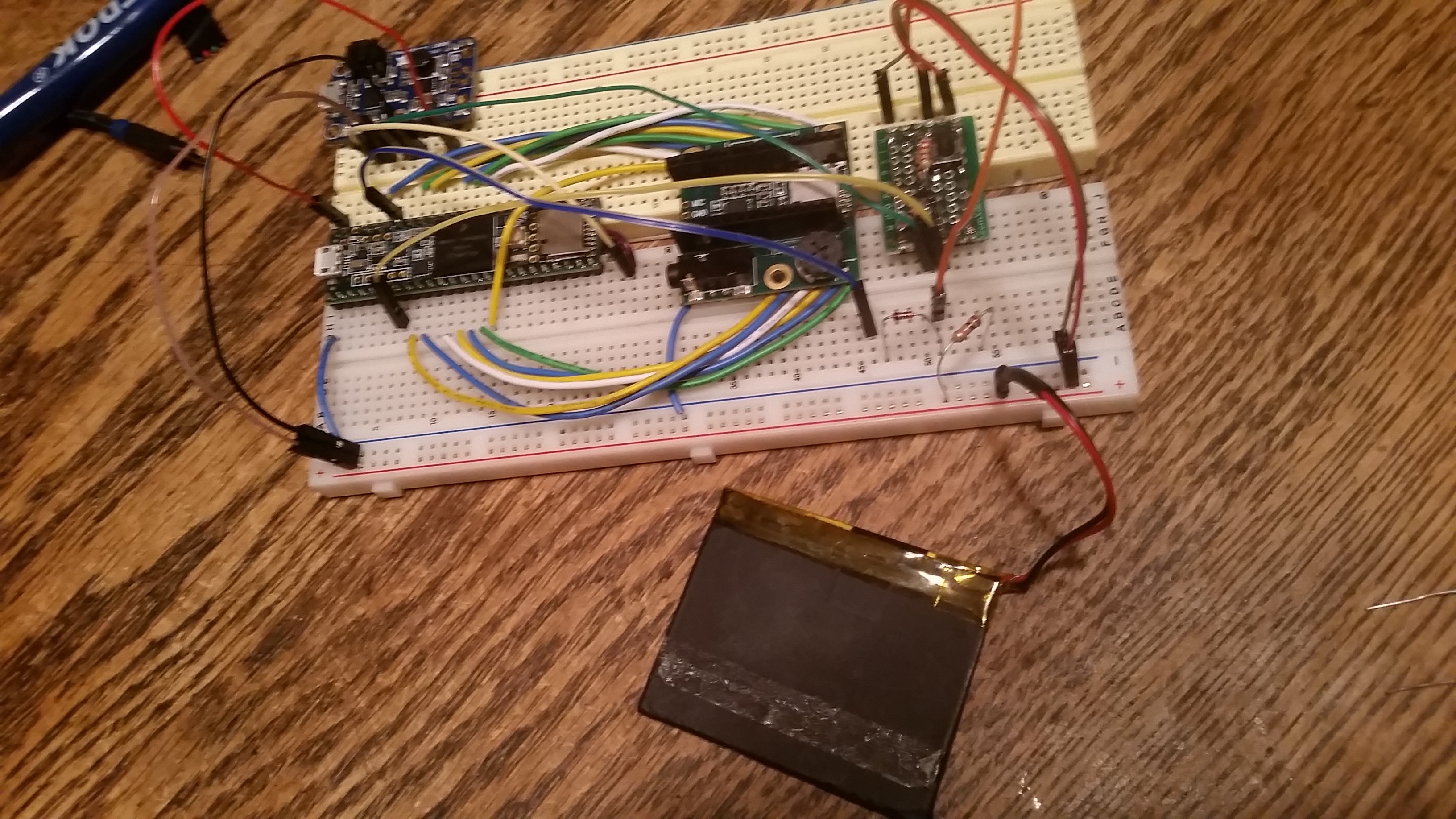
09/12/2018 at 05:27 • 0 commentsI received a new Teensy 3.6 and an Adafruit PowerBoost 1000C LiPo charger board and did some experimenting today. I'd like this project to run from a single cell LiPo, and charge when plugged into USB. I'd also like to incorporate a soft power button that I've used on a few other projects.
![]()
Testing with a 900mAh LiPo battery. I've broken out the Teensy audio shield because I didn't want to install stacking headers on the Teensy. The small board on the right is the power control circuit described below. To run the Teensy in this configuration, a trace on the bottom of the board that connects the USB +5v to the VIN pin must be cut. After that, it's possible to access the USB voltage from the VUSB pin, and power the board separately from the VIN pin. Because I'm prototyping in a breadboard, and the VUSB pin isn't breadboard friendly, I soldered a jumper onto the cut trace and secured it with tape. This jumper gets plugged into the breadboard at the far end and can be used for a charging voltage.
The Adafruit PowerBoost board combines an MCP73871 charging IC with a tps61090 boost converter, and breaks out status pins, battery voltage, etc. I'll use this board for prototyping and build a similar circuit into my finished design.
The soft power on feature takes advantage of the enable pin on the boost converter. A pushbutton connected to battery voltage will momentarily turn on the boost converter and boot the Teensy. The startup code can then pull a pin designated as power control (PCTL) HIGH, which is fed back into the enable pin. When the button is released, the Teensy keeps itself turned on through PCTL. With the addition of a couple of diodes, the button can also be read through and additional pin while the device is on. In this case, the battery voltage could be as high as 4.2 or as low as 3v, so the level must be clamped to 3.3v, and an ADC pin works best. When the Teensy wants to shut down, it sets the PCTL pin to LOW and the boost converter is disabled.
-
Building the button pad
09/11/2018 at 07:30 • 0 comments![]()
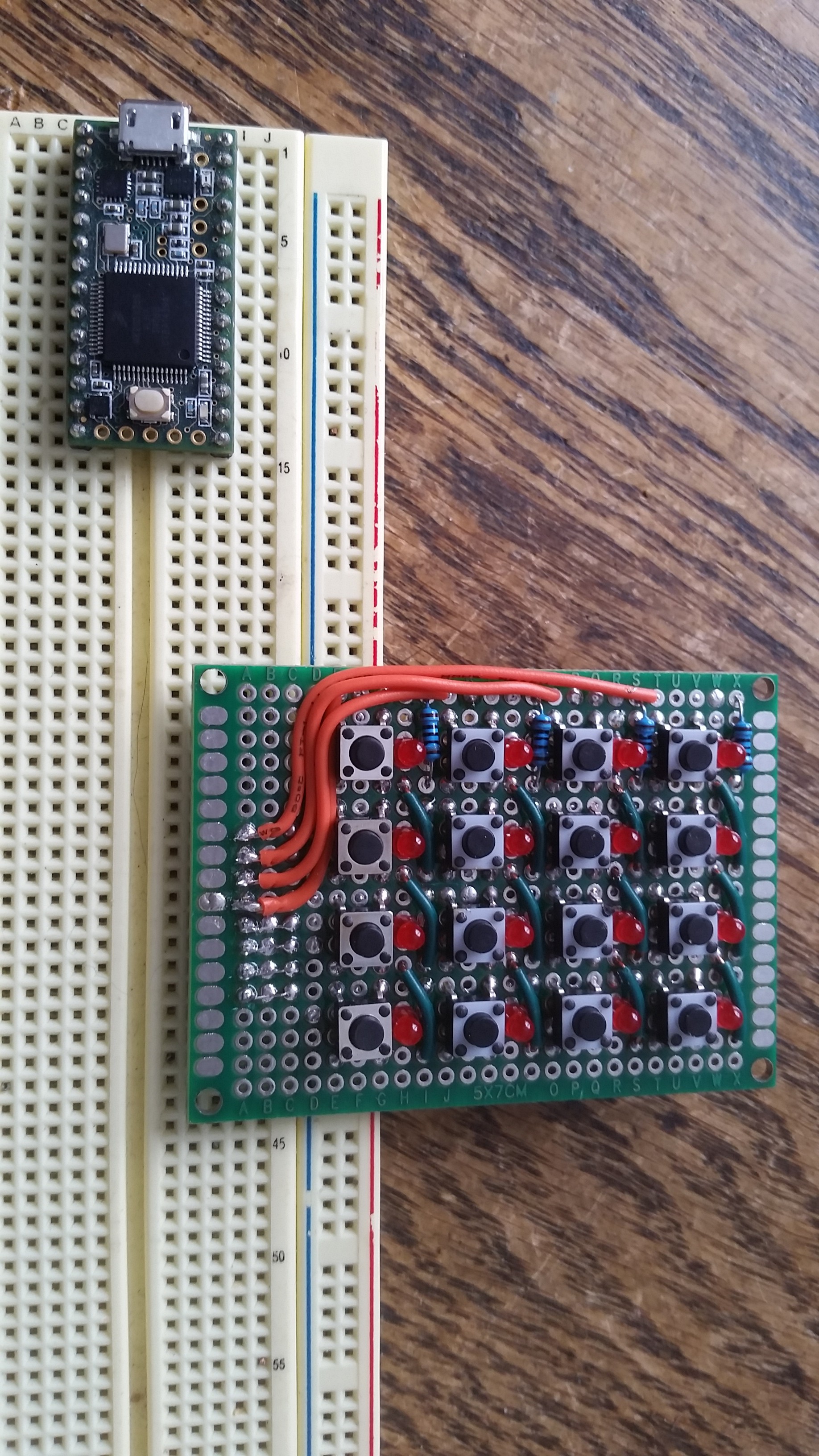
Multiplexed button/LED board I wanted to create a button pad with at least 16 pushbuttons, and ideally, an LED per button to show status. The easiest way would be a Teensy pin for each button and LED, but that would be at least 32 gpios. The Teensy 3.2 I had on hand didn't have anywhere near that many available unless I soldered wires on the bottom. So I thought it would be a fun challenge to build a multiplexed board that uses on 8 gpios. The rows and columns each get a pin. The columns are connected through a single diode with it's cathode connected to the Teensy. The rows of LEDs are also diodes, so altering the direction of current flow will either light the LED at the row/col junction, or test the switch.
The code to read such a multiplexed beast was somewhat tricky at first, but came easy once I proved the concept. The grid is scanned in a nested loop around 1000 times per second. First all 8 gpios are set to input mode to ensure all LEDs are off and no current is flowing. The LEDs are then scanned, by row, then by column. If the current LED should be on, the corresponding row is set to output mode, HIGH and the column is set to output mode LOW. onIf it's supposed to be off, no pins change. Each led has 48us to stay on, and is then turned off by resetting it's row/col to inputs. At 1000 iterations per second, this give the illusion of the LEDs being on solid.

This took a few hours to solder up. Then, a few times per second, the rows and columns are iterated again, but this time the rows are set to input, LOW. The columns are set to input with a pullup. Then the column is read with digitalRead(). If the value is high we're reading the pullup signal and the button is not pressed. If the value is low, the switch is pressed and the input is connected to the LOW output on the row.
Button press timestamps are stored in a 2 dimensional array so that software debouncing can be performed. If a button is pressed and the last press was less than say, 100ms ago, we ignore that press.
I found that when switching from LED mode to button reading mode, I needed to pause for one ms before performing the read. I assume that there was some charge built up in the rows and columns, and that needed to discharge before I could reliably read the inputs.
Teensy Beats Shield
An all-in-one, made to hack step sequencer built around the Teensy platform with LiPo charging, touch TFT, encoders, buttons, and RGB leds.