 Grant Giesbrecht
To design my equalizer, I started out with this circuit.
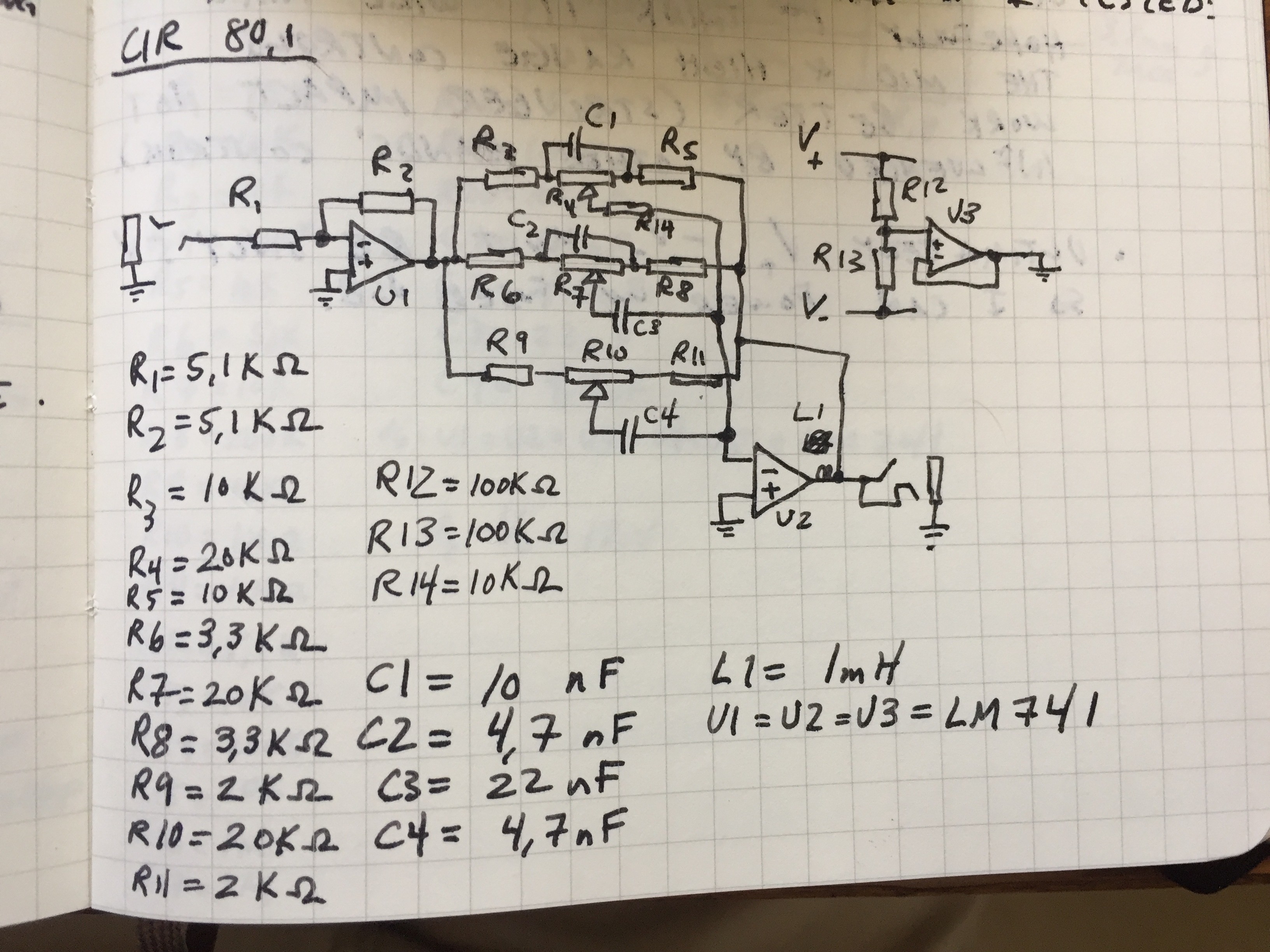
I threw it together on a breadboard and gave it a shot. As an initial test, I hooked it up to some speakers and my iPhone and listened to see how strong of an effect it had on my music. The bass channel worked very well, but the mid and treble channels didn't. Switching R4, R7, & R10 (the potentiometers) to 10kΩ improved the performance of the mid and treble channels, but they were still sub-par. Additionally, radio interference was a major problem.
To perform a more thorough analysis I created a C++ program that generated a test waveform for my Siglent SDG2042X arbitrary waveform generator to feed my circuit. The waveform was a sum of 8 frequencies. By running an FFT on the AWG's output and the output of my circuit I could see how my equalizer was effecting different frequencies. This is what the waveform looked like:
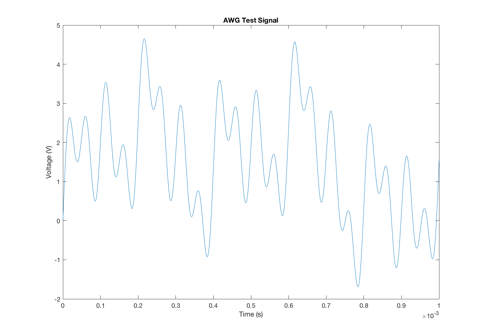
I used my scope's FFT to analyze the equalizer's effect. This prompted me to redesign the circuit with dedicated op-amps for each channel because I saw adjusting the potentiometer for one channel would effect the performance of the other two channels as well. The new circuit should eliminate that effect.
Discussions
Become a Hackaday.io Member
Create an account to leave a comment. Already have an account? Log In.