Close
0%
0%

Solar Water Heating Controller

Hot Water with STM8 eForth

Public Chat
Similar projects worth following
After almost 15 years of operation, my old homemade solar water heating controller (built with a PIC16F84) became unreliable, and both a quick fix and a permanent solution are now required. The first quick fix was a Sunday afternoon hack using a $0.80 STM8S103F3 breakout board and STM8 eForth. A full-featured permanent solution will be developed in this HaD project. Features will include diagnostics, functional safety, some kind of connectivity, and degraded operation modes.

An unexpected cold shower made it clear that I need a new controller for our solar warm water heating system ("split architecture" which is typical for installation in middle and northern Europe - thanks @Saabman for helping me understand that I had no idea how solar heating works in other parts of the world).

Of course this is a prime opportunity for applying the notorious STM8 eForth!

Our house is in Germany, in winter a (fossil fuel) heater is required for heating the top of the storage. The controller responsible for that is independent of the solar heating control, and it starts heating when the temperature at the top of the storage is below a certain threshold (typically in the morning on a sunny February day). An advantage of connectivity is that the weather forecast information can be used to change that behavior. A fail safe design is required but the usage of NTC sensors should make that easier. A second sensor for the storage will be required as a overheating protection: a failing storage sensor can lead to 400l of boiling water!

The old controller used a PIC16C84 and the code was borrowed from Microchip AN512 (plus LPF, serial interface etc). The temperature sensors I used then were KTY10 (2K type), the field-and-garden-variety sensors those days, and they're still good.

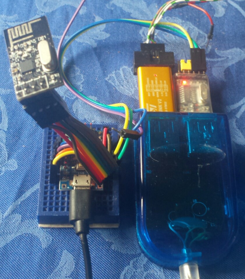
For a quick fix I reused the 5V power supply and the SSR pump control from the old PIC based solution. For now I use a $0.80 STM8S103F3P6 "Mindev" breakout board on a small "solderless breadboard" and some patch wires.

The solar collector and hot water storage have a KTY10 sensor each. Both sensors are in a voltage divider with a 2000R 1% "reference resistor" :

 (3.3V)
   |
 2000R
   |
   *------*---(PC4)
   |      |
 KTY10  KTY10
  COL    STO
   |      |
 (PA1)  (PA2)

The collector sensor is selected by PA1, the storage sensor (middle sensor in the picture) by PA2. A 3rd sensor, storage top, will be selected by PB4.

The first hack "solar.fs" had the following features:

  • linearisation and low pass filer for both sensors
  • robust measurement in a background task
  • safety limit for the storage temperature
  • 820 bytes code size (> 2500 bytes free!)

The second hack "solar-nrf24.fs" uses the STM8-nRF24L01 library to add some basic connectivity.

My prototype solar controller and the receiver are connected to an 8-pin nRF24L01+ module (more likely a clone) as follows:

Pin nRF24L01Signal nRF24L01 STM8S103F3
1
(Gnd)
(Gnd)
2
(VCC)
(3.3V)
3CE
PD2
4/CSN
PD3
5SCKPC5
6MOSIPC6
7MISOPC7
8IRQPC3

For connectivity I see two cheap standard options:

  • ESP8266 (e.g. ESP-01) connected to the serial interface
  • nRF24L01+ connectivity developed here

I plan to design a PCB that offers both options

  • Looking for an enclosure

    Thomas11/10/2018 at 21:12 0 comments

    The PCB core design now fits many use cases. It's time to think how to source cheap enclosures. On the usual Chinese hobbyist sourcing sites the G311/G212 box with dimensions 115x90x55mm³ is widely available. It's a nice fit for a 100x80mm² PCBs (minus a few cm²).

    Such a boxes are currently on offer less than $3.50 with "free shipping". A preliminary check of the "mechanical engineering constraints" looks promising (e.g. M16 cable glands for mains voltage and pump wiring fit in).

    This box is maybe also a good fit for other control and monitoring applications.

  • Starting to Design the SolBoard

    Thomas10/28/2018 at 20:43 0 comments

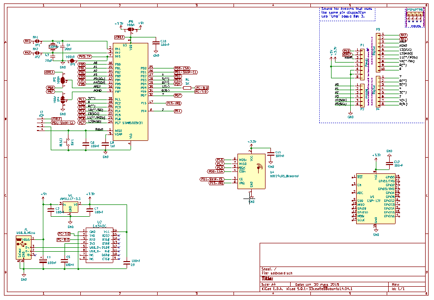
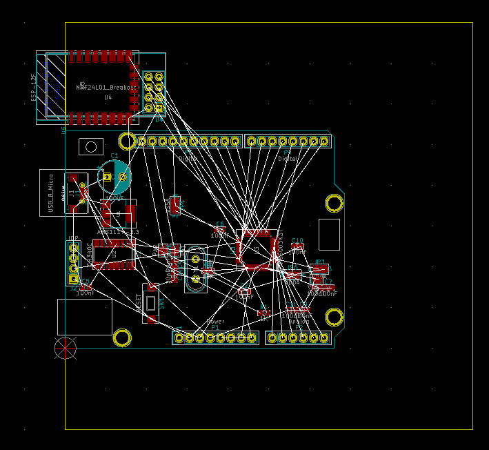
    I started designing the core around STM8Sx003K3T6 (or alternatively STM8S105KxT6), and since I'd like to have a board for all kinds of "remote stuff" I decided to add an Arduino style connector, an ESP-07S/ESP12F socket, a CH340 USB/serial converter, and other goodies.  

    I decided to assign GPIOs to the Arduino header so that using cheap Arduino Shields is possible (Arduino Playground's Shield Pin Usage table was very helpful). Of course, one-to-one GPIO grouping isn't possible but a bit of glue code can fix that.


    While using Arduino Shield shall be possible, the SolBoard should make best use of the 10x10cm² panel size that budget PCB houses "hand out" to the masses. I hope to find the right mixture of features and pragmatism so that my solar controller board can also be used as a prototype board or for other logging or control use cases.

    The general layout of the board is this:

    • East:
      • RF, USB and control inputs,
    • West::
      • SSR, power supply and heavy-duty connectors
    • North and South:
      • 5mm spacing for a 100mm wide "aluminum profile case",
      • maybe a small breadboard area

    There are now some things to decide:

    • Which power supply module to use?
    • How to design surge and overload protection?
    • One or two SSRs?
    • How to do milling for insulation?
    • Which type of ESP8266 and nRF24L01 module (e.g. external or PCB antenna)

    I would be happy to receive some advice from the community!

  • Learning to know cause and effect

    Thomas09/27/2018 at 09:30 0 comments

    Yesterday I mentioned a possible "net loss" due to switching on pump: a temperature drop in the storage. I was guilty of jumping to a questionable conclusion.

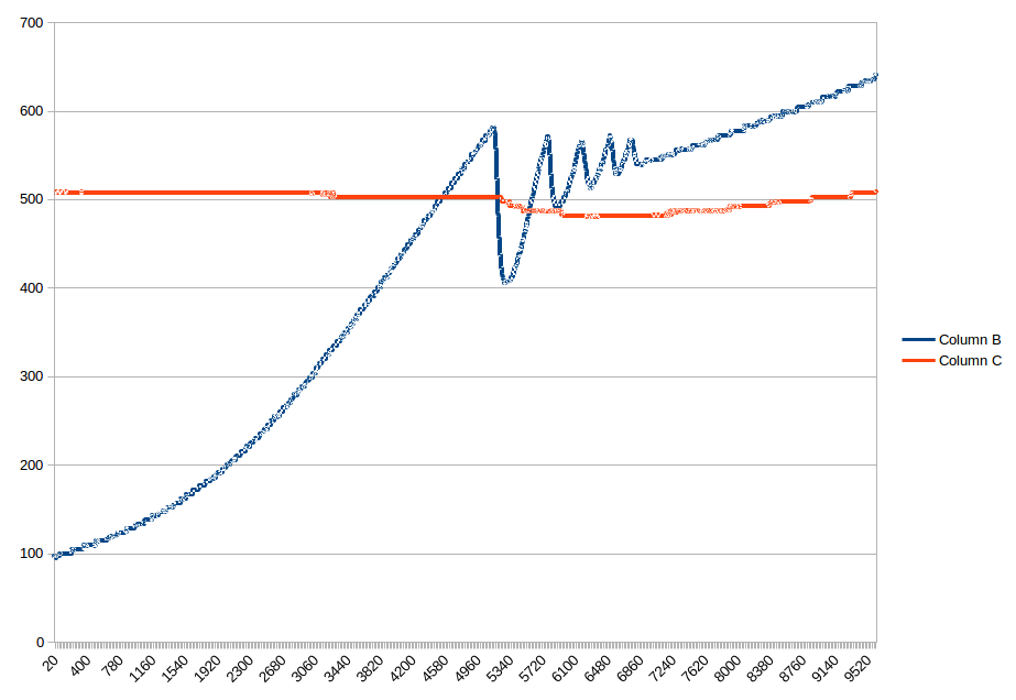
    This what I observed this morning:

    If you compare it to the image in yesterday's log, the effect is even more pronounced. The main difference is that more hot water had been consumed yesterday evening. I now offer a different explanation: the sensor is above the heating coil in the storage, and (more heavy) cold water is below the point ofmeasurement. By activating the pump, the coil exposes the (warmer) water above to a lower temperature. The net effect is that cold water at the base of the storage gets heated.

  • Things are getting interesting once you have data!

    Thomas09/26/2018 at 10:31 0 comments

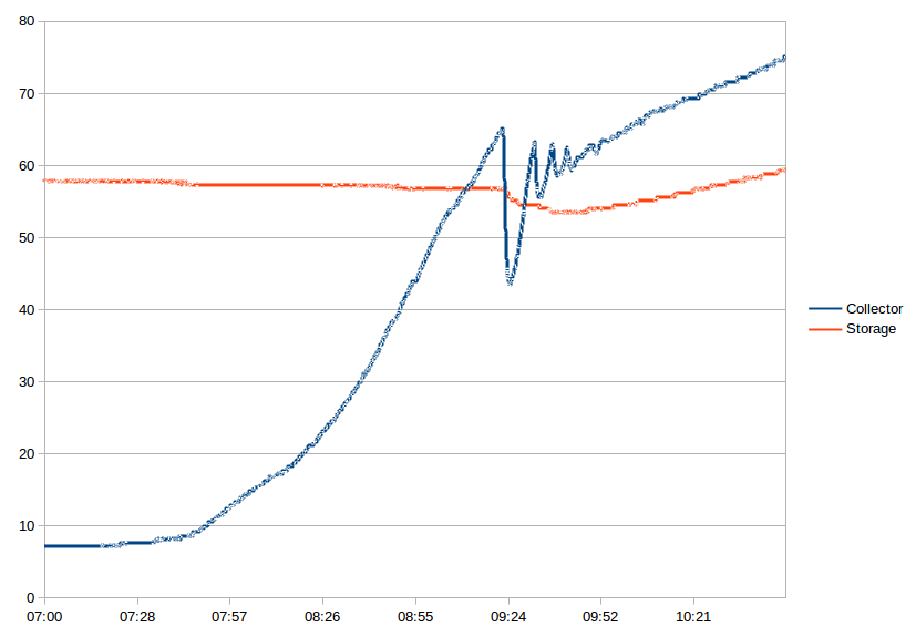
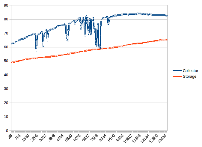
    This is an interesting finding: starting up the solar heating circulation pump in the morning comes at a cost: the temperature as measured above the heater coil in the storage initially drops by several degrees [°C], and it takes full hour of late September morning sun for it to return to the initial value. This could mean that when the sky is cloudy starting the heating can be a net loss!

    Of course, this also shows potential for innovation:

    • in order to offset the energy needed to heat up the cold transfer fluid in pipes from roof to basement, a much higher threshold for the difference between storage and collector can be used after extended inactivity of the pump (the threshold effective in the diagram is 8°C/5°C on/off )
    • use weather forecast information from the Internet to decide if a positive effect of using the solar collector is to be expected (which, based on these observations, is unlikely on a cloudy November day)

    In any case, I wouldn't have thought that a system this simple can show interesting behavior!

  • Wireless data transmission: day one

    Thomas09/25/2018 at 09:12 0 comments

    One of the effects of having a wireless link to a solar water heating is that one can ponder about technical properties one would never have known they exist, e.g. initial temperature drop when the system starts up on a sunny morning, heat transport limitations or not enough noise to the sensor signals. It's good to know that none of that really matters - when the sun shines heat will be transported, and no optimization can replace sunshine :-)

    The graph shows the collector and the storage temperature (in °C). The time span is roughly from 11:30 to 15:20 CEST (25/Sep/2018, Southern Germany, 5m² collector, 300l storage). The effect of clouds is easily visible. The storage temperature in the early morning was about 45°C, at the time of writing (15:40) it was 66°C.

  • Wireless transmission of Solar Collector and Storage Temperature via nRF24L01+

    Thomas09/24/2018 at 14:05 0 comments

    I combined the simple solar controller code gist with the PingInt code from the stm8ef-nRF24L01 repository into a solar-nrf24 gist. This is experimental but for now it works.

    The output from Pong looks like this:

    Solar   710     556        0     96
    Solar   710     556        0     96
    Solar   710     556        0     96
    Solar   710     556        0     96
    Solar   710     556        0     96
    Solar   710     556        0     96
    Solar   710     556        0     96
    Solar   709     556        0     96 
    

    The text "Solar" and temperature from the collector and the storage sensors (by 10) are transferred as plain text.

    This is what I use as a nRF24L01 receiver:

    All relevant links are in the Gist comment.

View all 6 project logs

Enjoy this project?

Share

Discussions

Saabman wrote 09/27/2018 at 04:22 point

Split systems are very common here in Australia as well mainly because people don’t like the look of the tank on the roof.  I have a issue of the water freezing in the water supply to the tank. 

The close coupled system I have uses glass tubes like a vacuum insulated flask in which the water is heated from the sun. The glass tubes attach directly to the tank. Most sunny days even through winter the water will boil ( temperatures between -6 and +10degC ) 

The booster I was referring to is a heater element to “boost” the water Temperature on cloudy days.

I was particularly interested in your data because I use a heat exchange on a slow combustion wood heater to heat the water on cloudy days but I have noticed if the fire is not hot enough I loose more water temperature due to water cooling in the pipes between the tank and the fire. Which is a similar issue you have noted when your pump first starts of a morning. My system currently relies on a thermosiphon between the fire and the tank but I have been considering adding a pump to have better control over the flow and minimize the heat loss. 

  Are you sure? yes | no

Thomas wrote 09/27/2018 at 05:43 point

Thanks, that explains a lot! I had asked myself which device in a thermosiphon prevents boiling ;-) I would have expected calcium carbonate deposits to build up in the tank. Is that a problem that people observe?

The "boost device" in my split system is in the basement, the burner about 1m away from the storage. Currently it's activated at a lower threshold of about 45°C and one of my concerns is that it's often active in the morning before the solar system has had a chance to do its job.

In order to reduce unnecessary pump operation (and hence electric energy consumption) I'm now also thinking of raising the temperature difference between storage and collector when no increase of the storage temperature can be observed. I have, however, no idea if there isn't a net energy transport into the storage independent of the point of measurement. Measuring the temperature difference between the incomming and the return pipes might bring clarity.

  Are you sure? yes | no

Saabman wrote 09/25/2018 at 10:59 point

Hi Thomas,

how do you find the efficiency of the split system?

How much energy goes into running the circulation pump even better do you have logs for pump run time? and booster run time

Ive been monitoring my Close coupled system and find it very good - boosting is required only a few days a year 

https://hackaday.io/project/15228-solar-water-heater-monitor

  Are you sure? yes | no

Thomas wrote 09/25/2018 at 12:00 point

I'm not familiar with the terms "split system" and "booster" - could you please explain?

As for data, I just started my little project and I don't have proper data logging (this will, of course, be implemented in due time). As for the pump, the type of the one that's installed in my heating system is known for less-than-optimal efficiency. It has 3 manual speed settings, and I selected the one in the middle that consumes 61W - when the storage temperature is low it basically runs while the sun is shining (or until the storage temperature reaches the upper limit). Optimizing the duty cycle so that it only runs when it's worth the effort is certainly a good idea. Electric energy is too expensive for heating water but on a sunny winter day the solar collectors manage to raise the temperature to up to 50°C.

  Are you sure? yes | no

Thomas wrote 09/26/2018 at 05:33 point

I found the terms "booster" used where the pressure of the water outlet is to be increased. In my cases, the water pressure from the facilities is high and no booster is required. Instead a so called "circulation pump" may be used: in feeds water from the red warm water line in the Wikipedia picture above back to the storage. I don't use it, though.

With "split system" I now understand that it refers to what's the normal system around here. In more sunny countries, like Portugal, Greece, or Spain one is likely to find the "thermosiphon" type. In the northern European countries winters are much too cold for that (the water in the siphon would freeze) and one has to split collector from "storage" (heat transfer fluid contains an antifreeze compound which is detrimental to heat capacity and hence decreased transfer efficiency).

The efficiency trade-off is compensated by doubling the surface, and the lack of sunshine in Winter (the sun inclination is below 20° for 8 weeks here!) by adding some more surface, and by using bigger storages (get the most of a sunny day in February or November). The consequence is excess heat in the months from April to September.

  Are you sure? yes | no

Thomas wrote 10/28/2018 at 21:06 point

Two weeks ago I was  in India, and there I had an opportunity to closely examine a close-couple system. If sunshine is abundant a solar heating system can be a lot simpler :-)

  Are you sure? yes | no

Similar Projects

Does this project spark your interest?

Become a member to follow this project and never miss any updates