 Alex Brown
I now have everything I need to get started on revealing the secrets of the Psion SSD Port. So, here's what I've been up to this morning.
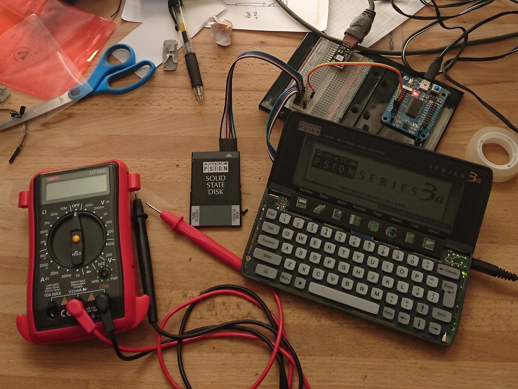
Rather than pull apart my "production" 3c, I've decided to get to work on a slightly broken 3a. I don't like the idea of doing something dumb thanks to my inexperience and blowing up my 3c. The 3a's battery compartment is in a pretty bad way, but it powers on quite happily with a Series 3 external PSU. So, I pulled it apart and got to work.
For some reason, this 3a smells really strongly of some spice or other, possibly cumin. It's not pleasant and the unit could really do with a bath in alcohol.
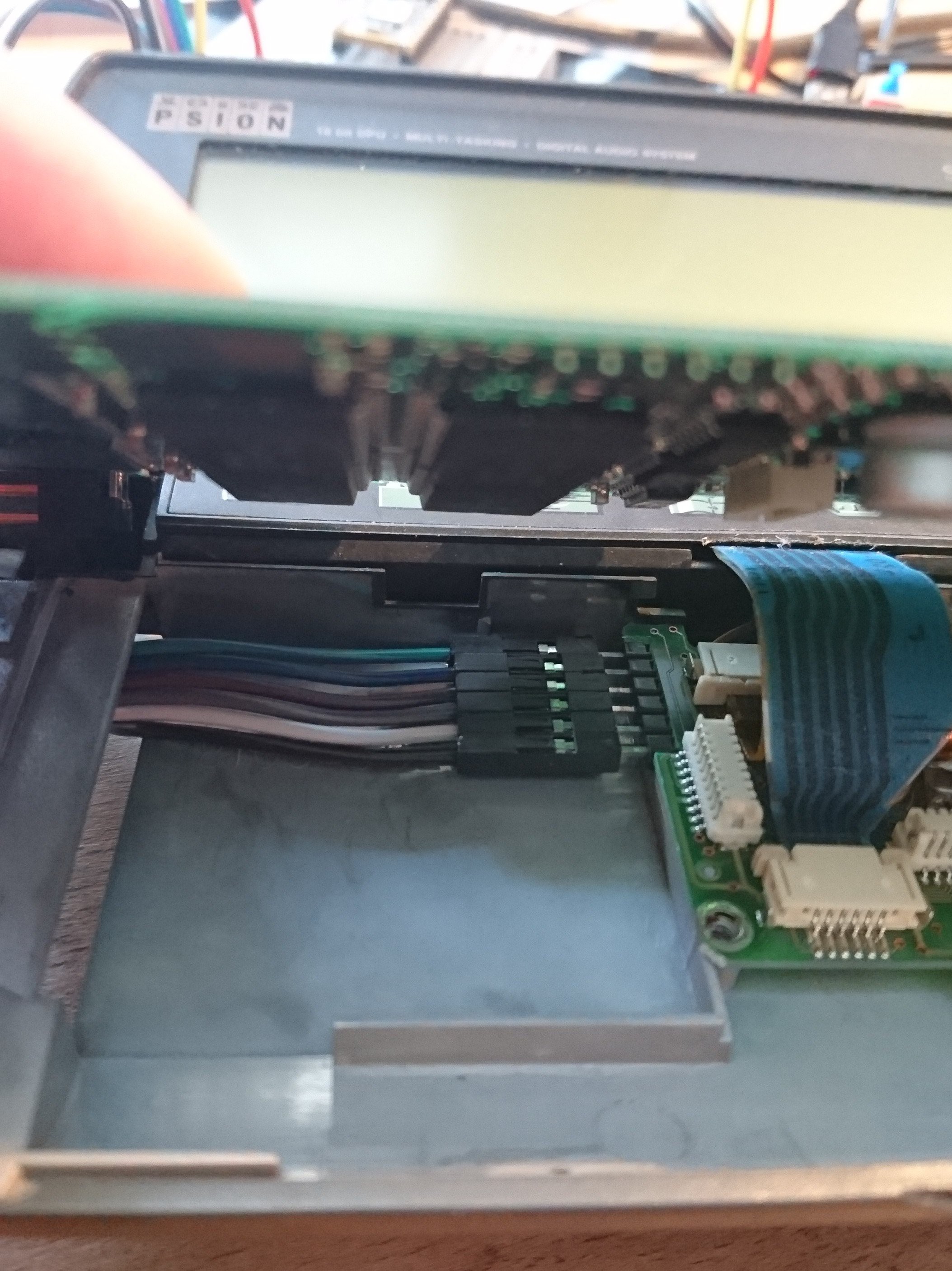
I removed the door for Port A and directly attached six jumper leads to the six pins of Port A. The other ends of the leads were plugged into a solderless breadboard. I then ran a further six jumper leads from the breadboard to my SSD. Keeping my fingers crossed that I hadn't miswired anything (it's currently my only SSD) I powered up the 3a and... it still worked!
My next step was to find out what each pin did. I had already found the SSD pinout using this post from comp.sys.psion.misc, so I used that as basis and used my multimeter to test the voltages on pins 3 to 5. So, here's the updated pinout, using the post on comp.sys.psion.misc as a basis.
| Pin | Name | When the 3a is on | When the 3a is off |
|---|---|---|---|
| 1 | CLK (input to SSD only) | Clock (+5V) | 0V |
| 2 | GND | GND | GND |
| 3 | Vbackup | +3.75V DC | +3.75V DC |
| 4 | Vpp (for Flash programming) | +15.75V DC | +9V DC |
| 5 | Vcc | +5V DC | 0V |
| 6 | DATA (bidirectional) | Data (+5V) | 0V |
Interestingly, the Vpp voltage drop isn't instantaneous, taking just under 10 seconds to drop from 15V to 9V.
So, I have a few questions:
What's the point of Vbackup?Why does Vbackup stay live when the unit is turned on?- Why does Vpp drop to 9V when the unit is off? Why doesn't it go off completely?
- Is there a reason Vpp takes time to drop, or is it just a capacitor taking time to discharge?
UPDATE: I now realise that Vbackup is there to maintain power to RAM SSDs so they don't have to rely on their own internal CR1620 batteries when inside the Psion. This answers questions 1 and 2 - that power is needed even if the Psion is turned off. My guess is that RAM SSDs have Vpp disconnected, Flash SSDs have Vbackup disconnected, and ROM SSDs have both disconnected. It is also worth noting that Vbackup and Vpp are live even if there is no SSD connected and the Psion is off, albeit with Vpp running at 9V. This might prove useful in the future.
I felt it was now time to connect up my USB logic analyser and see if I could use PulseView to see the SIBO Serial Protocol at work. (The other device on the breadboard is an Espruino Pico, which I was using to generate signals to make sure the logic analyser was working.)
After trying various settings and finally setting the sample rate to 24 MHz, I managed to capture a conversation between the Series 3a and SSD.
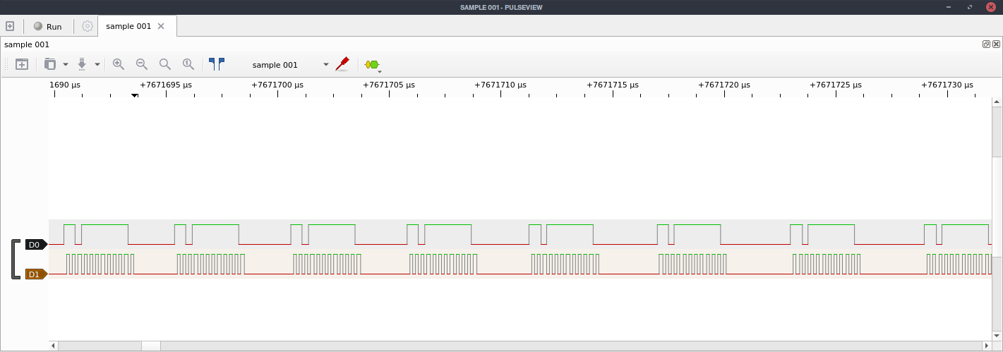
The top line is DATA and the bottom is CLK.
PulseView and its backend library sigrok have the ability to do some analysis on the signals they capture. There are plugins for all sorts of protocols, such as I2C, AC '97, SPI. This made me wonder how difficult it would be to write my own plugin for the SIBO Serial Protocol. After a quick look on Google, I found this:
https://sigrok.org/wiki/Protocol_decoder_HOWTO
So I think my next step is to see if I can write a protocol decoder for SIBO using the HDK document as a basis. It will help me to understand the protocol better for when I finally get around to building the first SSD prototype.
Discussions
Become a Hackaday.io Member
Create an account to leave a comment. Already have an account? Log In.