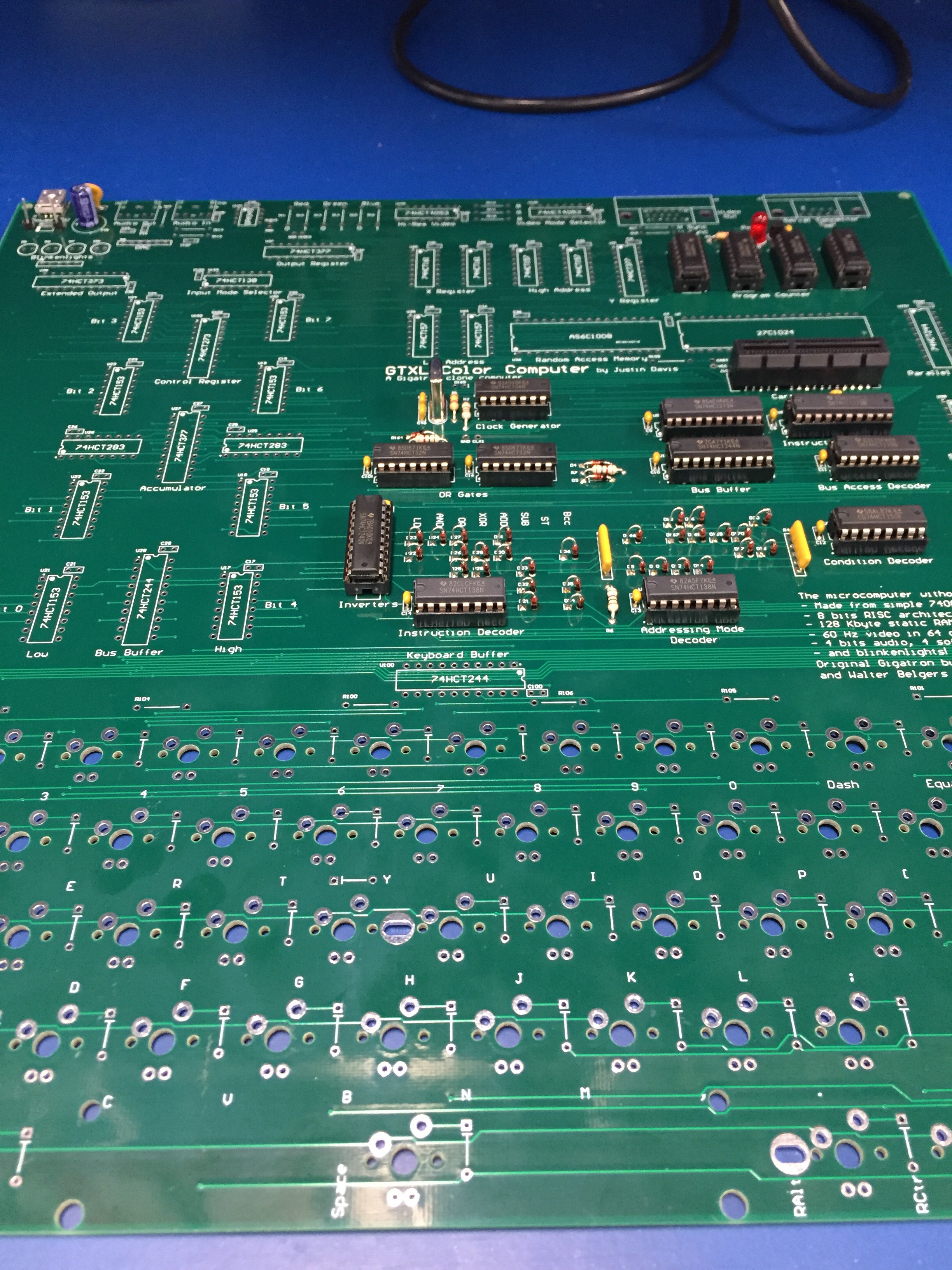
I've been building the GTXL one step at a time and checking as I go. So far, the power system, clock, program counter, IR/D registers, and control system is working.
I made one mistake with the diodes. The artwork is reversed, so I installed all the diode backwards. Installing (and removing) those diodes is pretty time-intensive, so it set me back quite a bit. But everything else is ok so far.
I'll probably do the ALU next followed by the X/Y registers. I want to build up and test all of the existing functionality before I move on to the added functions.
Discussions
Become a Hackaday.io Member
Create an account to leave a comment. Already have an account? Log In.
if you do sell the board or release the files I will be building one of these. One can’t have too many Gigatron’s.
Are you sure? yes | no
"I made one mistake with the diodes. The artwork is reversed, so I installed all the diode backwards. " Just out of curiosity, wouldn't you have inherited the right artwork from the original Gigatron KiCAD files?
Are you sure? yes | no
I started from scratch in Altium, so I had to make all of the parts that were not available in the default Altium library. There were no through-hole diodes in the library, so I had to make them manually.
Are you sure? yes | no
Wow! I didn't realize you did that. GOOD JOB!!! Your layout looks very similar to the original. Looking forward to you bringing the board up. Do you plan to release the layout in future?
Are you sure? yes | no