 Kelly Heaton
*This log is an extension of my last entry, so please start there if you want more information about how the following work of art was made.
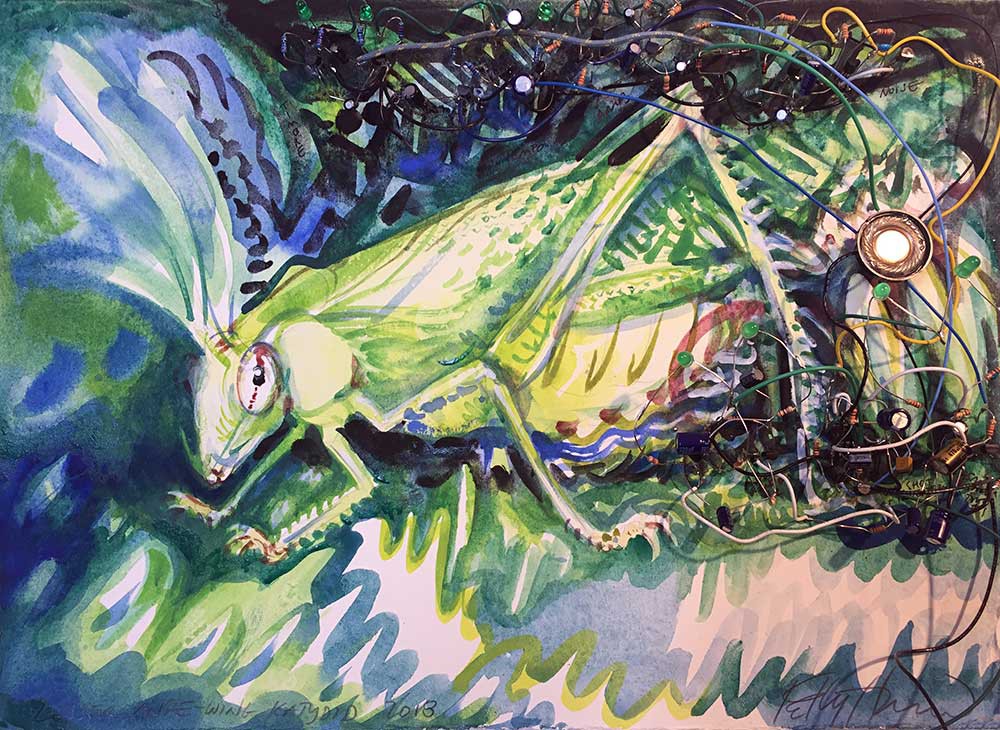
I finished breadboarding my circuit for a Lesser Angle-winged Katydid. Then I forced myself to document it with a schematic -- "forced" because my tendency is to go on inventing things and forget my design history, and I have learned the hard way that I must solder an instance of my schematic to be sure that it's accurate. It's all good, though, because building a permanent circuit gives me a future reference to use alone or in parallel with other sound-generating circuits. Many of my circuits are sensitive to noise, so I try to test them in combination before I send out board designs or embark on a larger piece.
I got into the habit of making these electrified watercolor studies in the days before I used software for schematic design and printed circuit board layout. You can see images of early works here. As time goes by, these studies help me to remember why I designed the circuit in the first place, like a bookmark for a time and place in life. I realize that there are more practical ways to archive a circuit, but it's a good excuse to make art.
Here is a video of the Katydid "rattling." I included a couple of crickets to give the Katydid's sound a more natural context.
To conclude this log, it occurs to me that some of you might not have drawing or painting skills. While I can't teach you to be an artist, I can suggest this useful hack: project an image and trace it. Please refer to the instructions associated with this project for more details on "How to draw if you have no artistic talent."
Discussions
Become a Hackaday.io Member
Create an account to leave a comment. Already have an account? Log In.