 Josh Wright
Well I started off with the Arduino and got myself set up to start sketching to it from my Macbook. It didn't take long and I had got the onboard LED on pin 13 flashing (my 'Hello World' to Arduino).
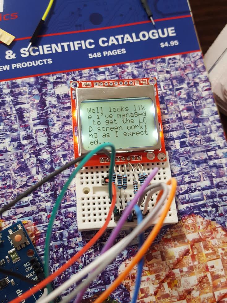
From there I sought to get started with the LCD. I followed a tutorial online (below) to get the LCD module working with my arduino, I then used that code as the basis to suit to my needs.
This will form part of the display output when I finally get my hands on the Gas Sensor module which should hopefully be by midweek.
To get the LCD to work I had to do the following in the LCDWrite() function which I found in the comments section:
SPI.transfer(data); //shiftOut(sdinPin, sclkPin, MSBFIRST, data);to
shiftOut(sdinPin, sclkPin, MSBFIRST, data);I also changed the code to the following within the lcdBegin() function
LCDWrite(LCD_COMMAND, 0x21); //Tell LCD extended commands follow
LCDWrite(LCD_COMMAND, 0xc8); //Set LCD Vop (Contrast)
LCDWrite(LCD_COMMAND, 0x12); //LCD bias mode 1:48 (try 0x13)
LCDWrite(LCD_COMMAND, 0x20); //chip is active, horizontal addressing, use basic instruction set
//We must send 0x20 before modifying the display control mode
LCDWrite(LCD_COMMAND, 0x09); //temperature control
LCDWrite(LCD_COMMAND, 0x0C); //Set display control, normal mode.
Once completed success:
Discussions
Become a Hackaday.io Member
Create an account to leave a comment. Already have an account? Log In.