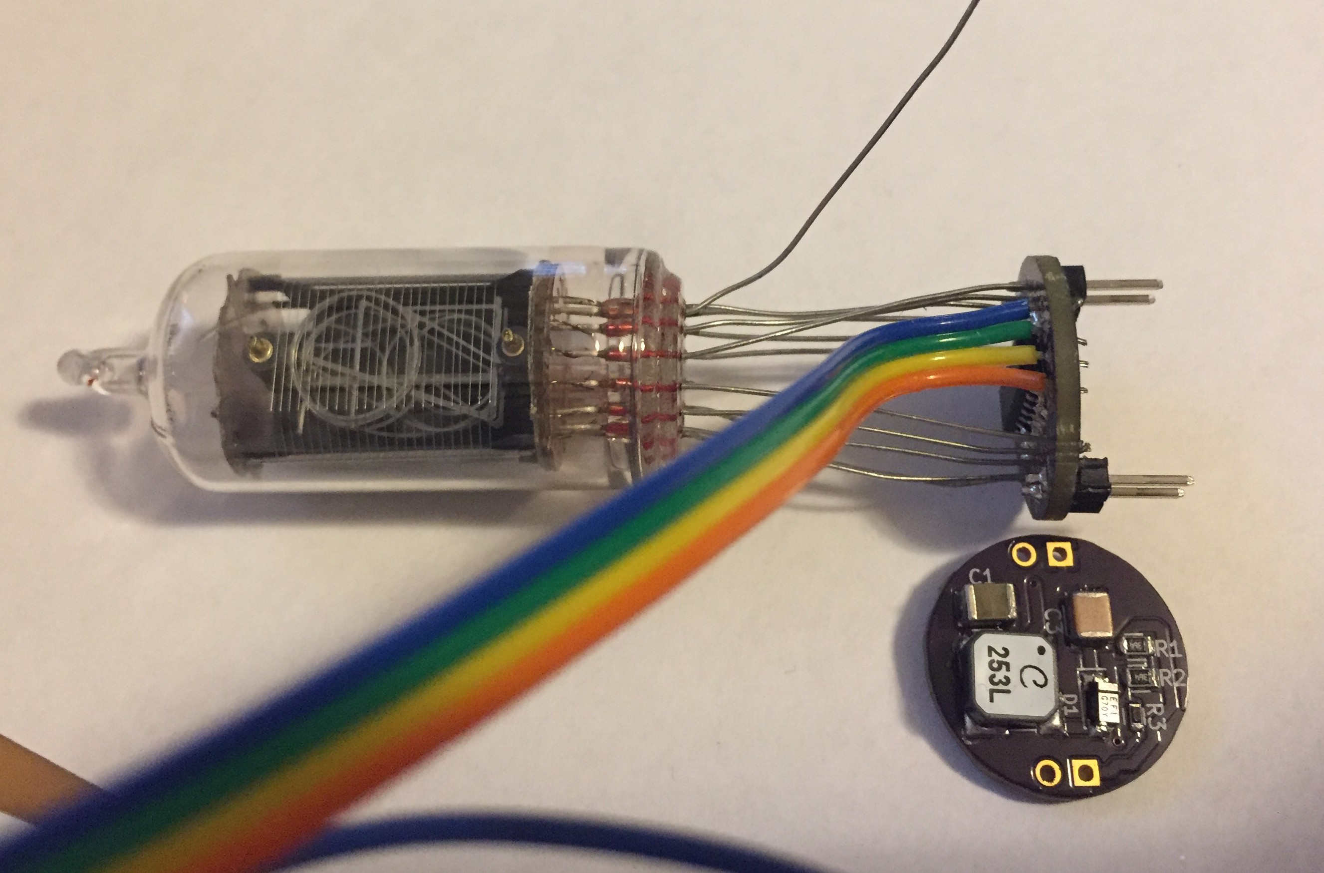
Here's some photos of the project so far. This first one shows the tube temporarily soldered to the driver board with the power supply. The ribbon cable is for programming the on-board ATTiny. In the final version, the tube will be soldered almost flush.

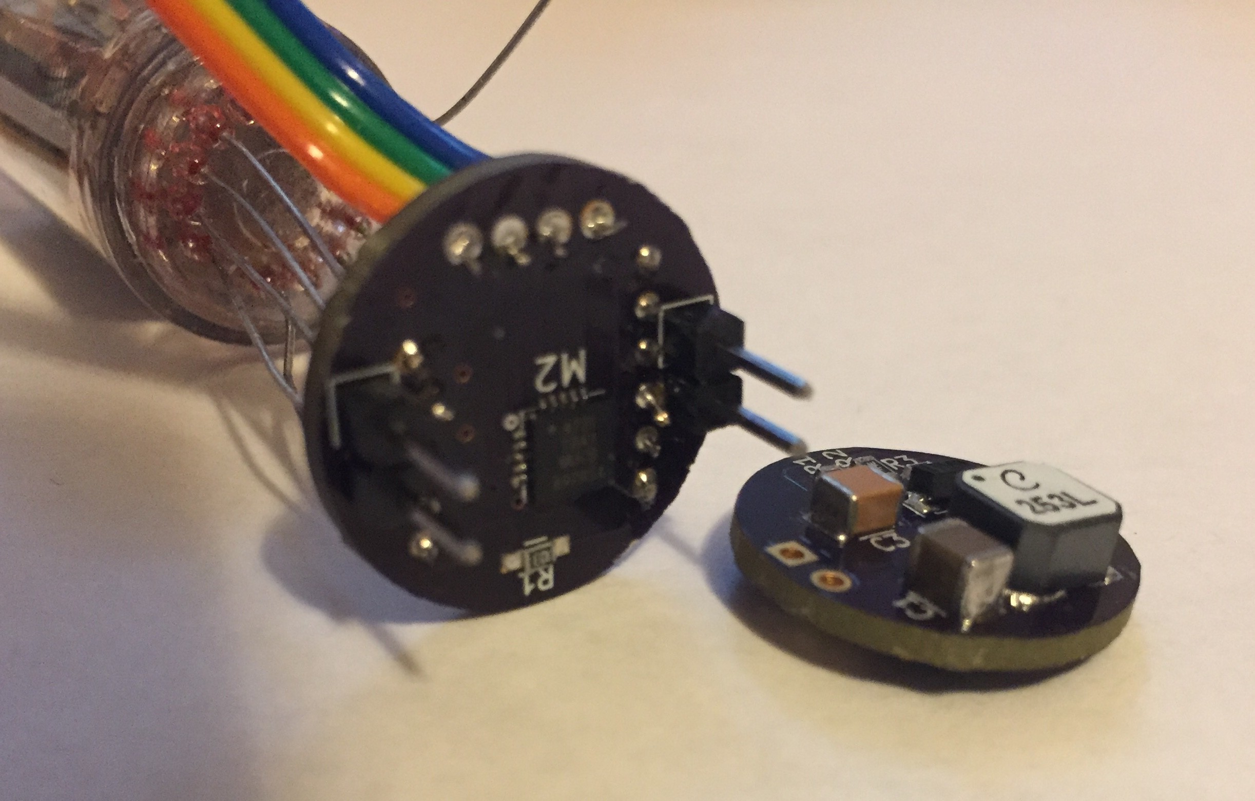
This is the bottom of the control board showing the ATTiny.

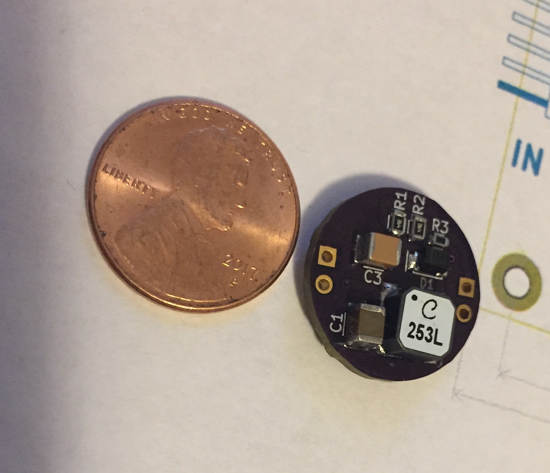
This is the top of the power supply, with a penny for size comparison. This board generates the 150V from the LiPo battery.

Here is a video of it in action. I'm open to ideas of what it should do, given that there are no sensor inputs (although there could be using the pins exposed for programming it).
 Paul Andrews
Discussions
Become a Hackaday.io Member
Create an account to leave a comment. Already have an account? Log In.