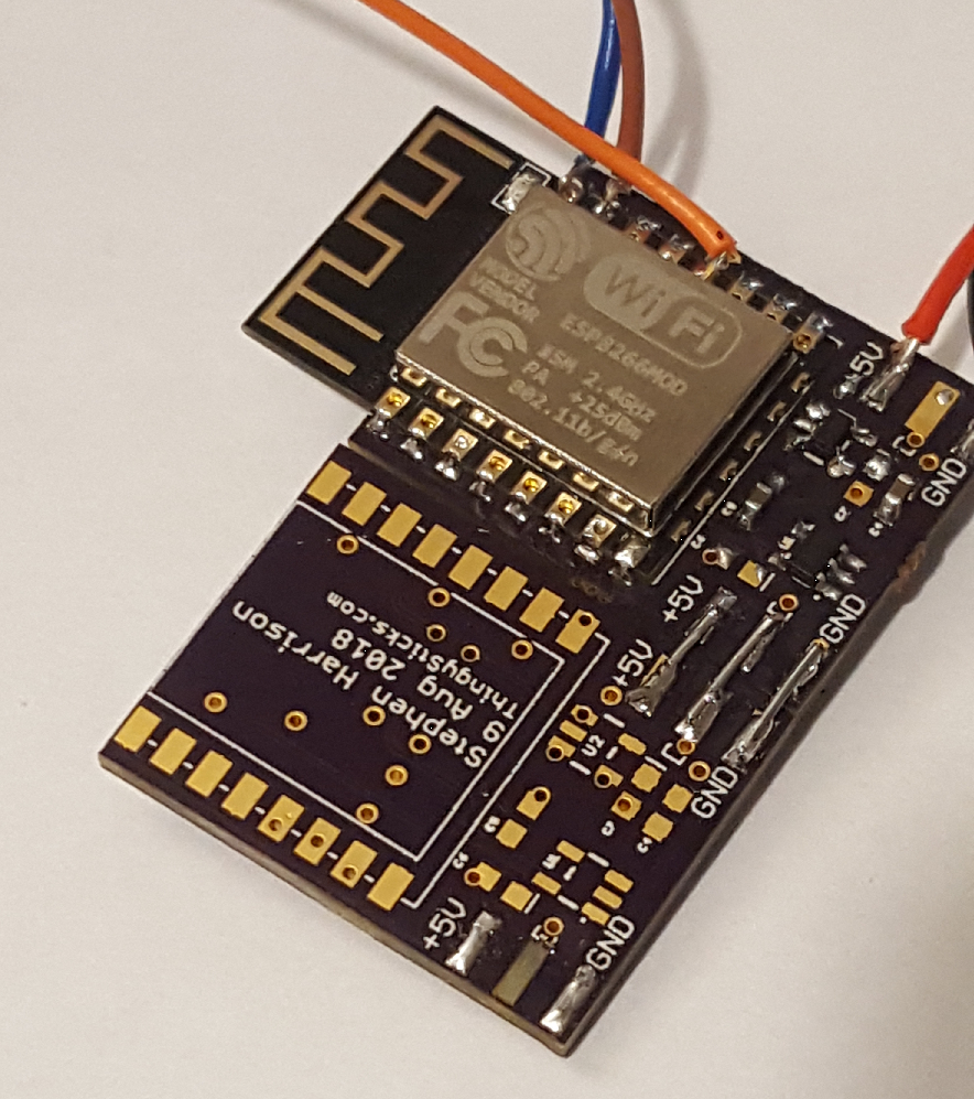
At the bottom of each digit is a 3 pad connector, this passes through power and the signal (D Out / D In) for the LEDs. These can be connected with a simple soldered wire link.
Child PCBs don't need any other components on the back, and just the WS2812B's and capacitors on the front. I'm not sure how many can be joined in series, but by supplying 5V externally a long series of digits can be made and limited through the available memory on the ESP8266.
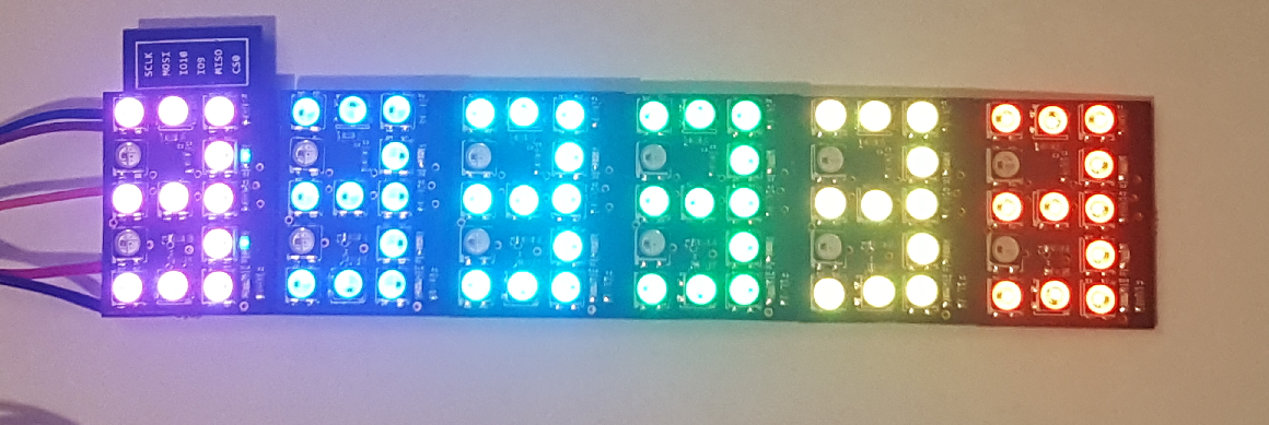
As an added bonus that the joints are reasonably flexible allowing the display to be curved.

Six IO7 digits joined in series. (Note the programming wires still attached, the digits are driven by the on-board ESP8266).

I used ESP8266 GPIO lines to control the colon and decimal digit for the display, this has the side effect that those LEDs are not functional on the child displays. For a clock a digit would need to be placed to the left of the parent and the DOut looped from the final digit to the first and the data written out of order to properly use the colon or decimal place.
 Stephen Harrison
Discussions
Become a Hackaday.io Member
Create an account to leave a comment. Already have an account? Log In.