Jack Flynn
-
Paper, glue and tweezers too!
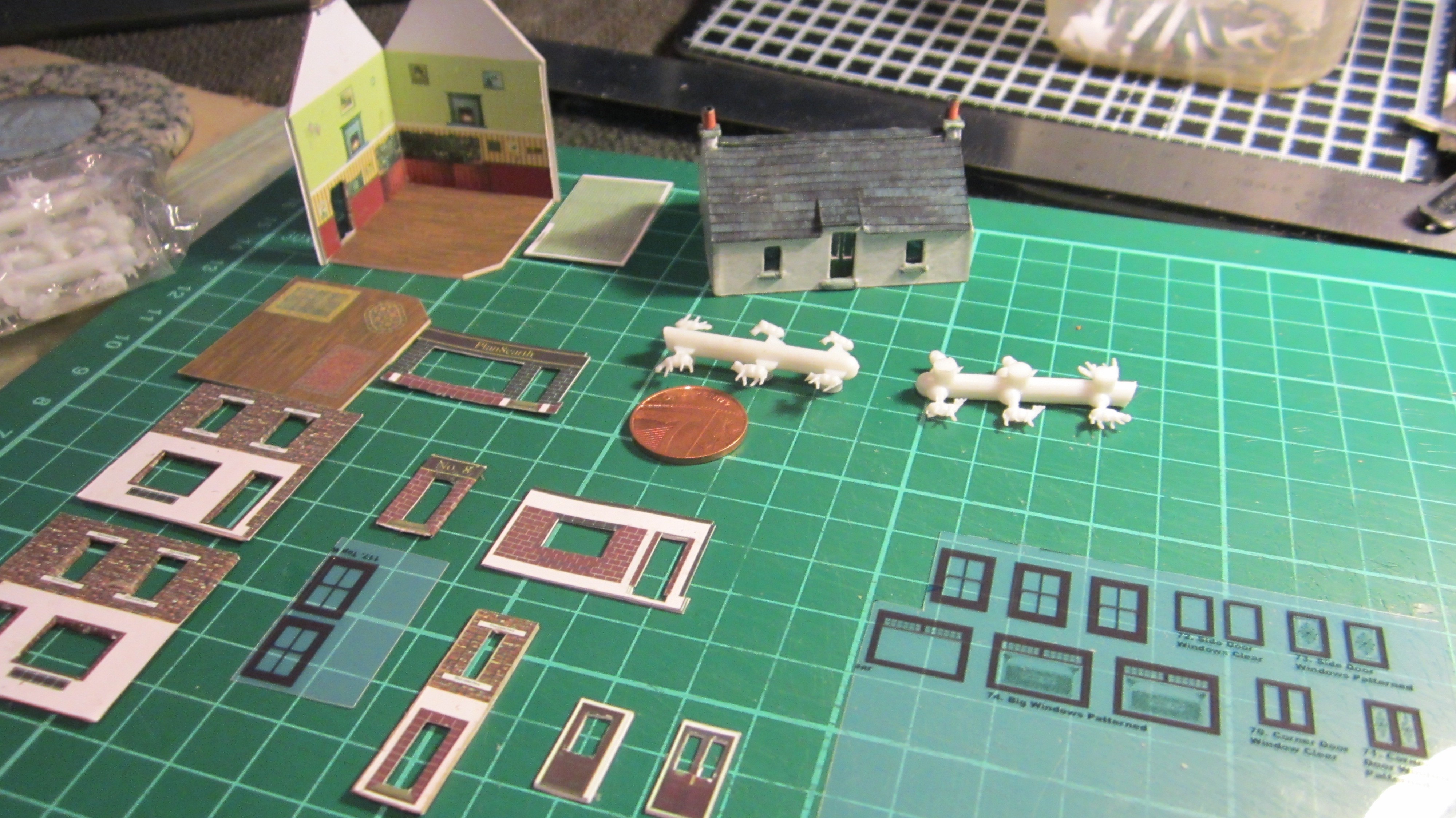
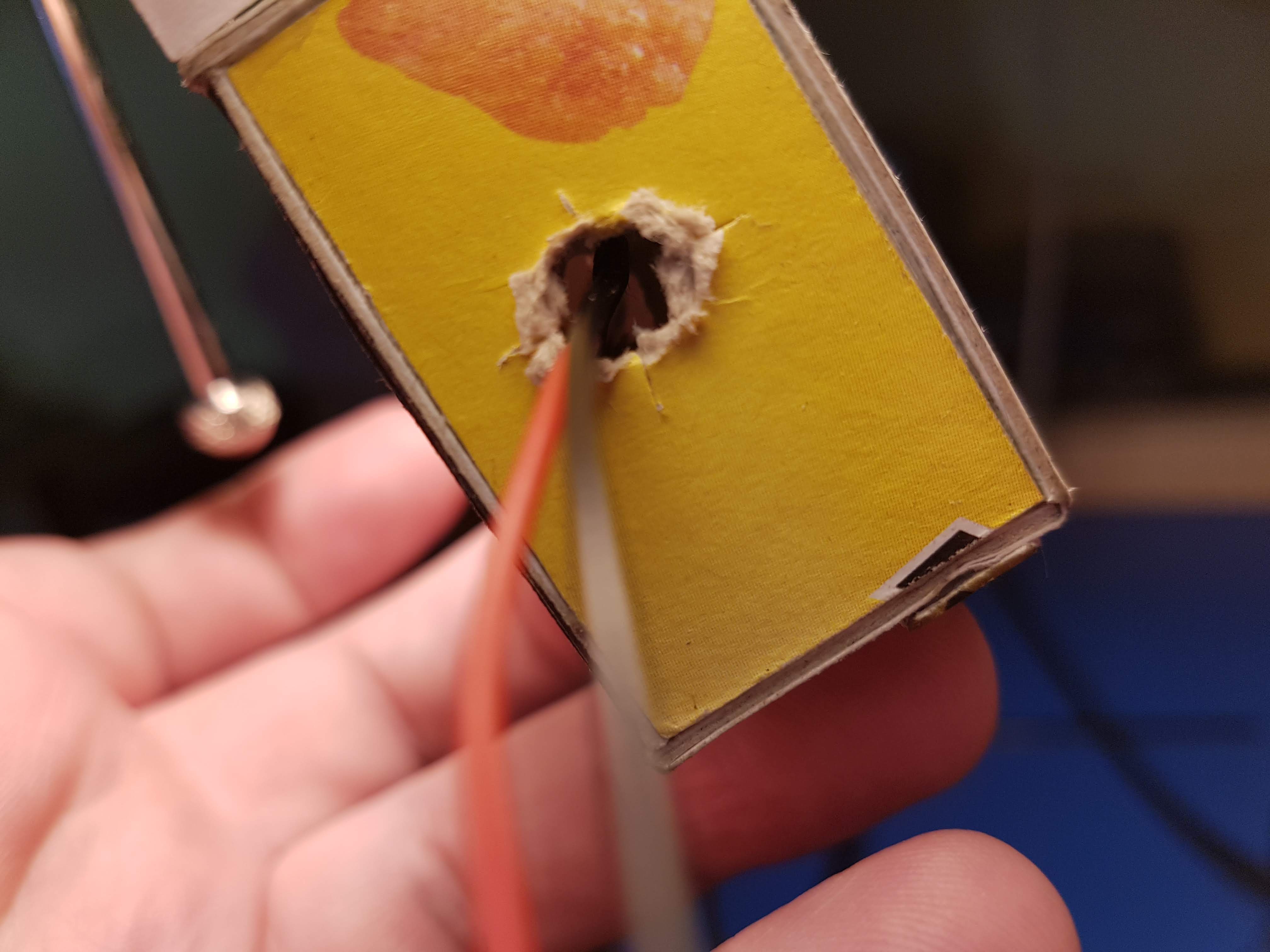
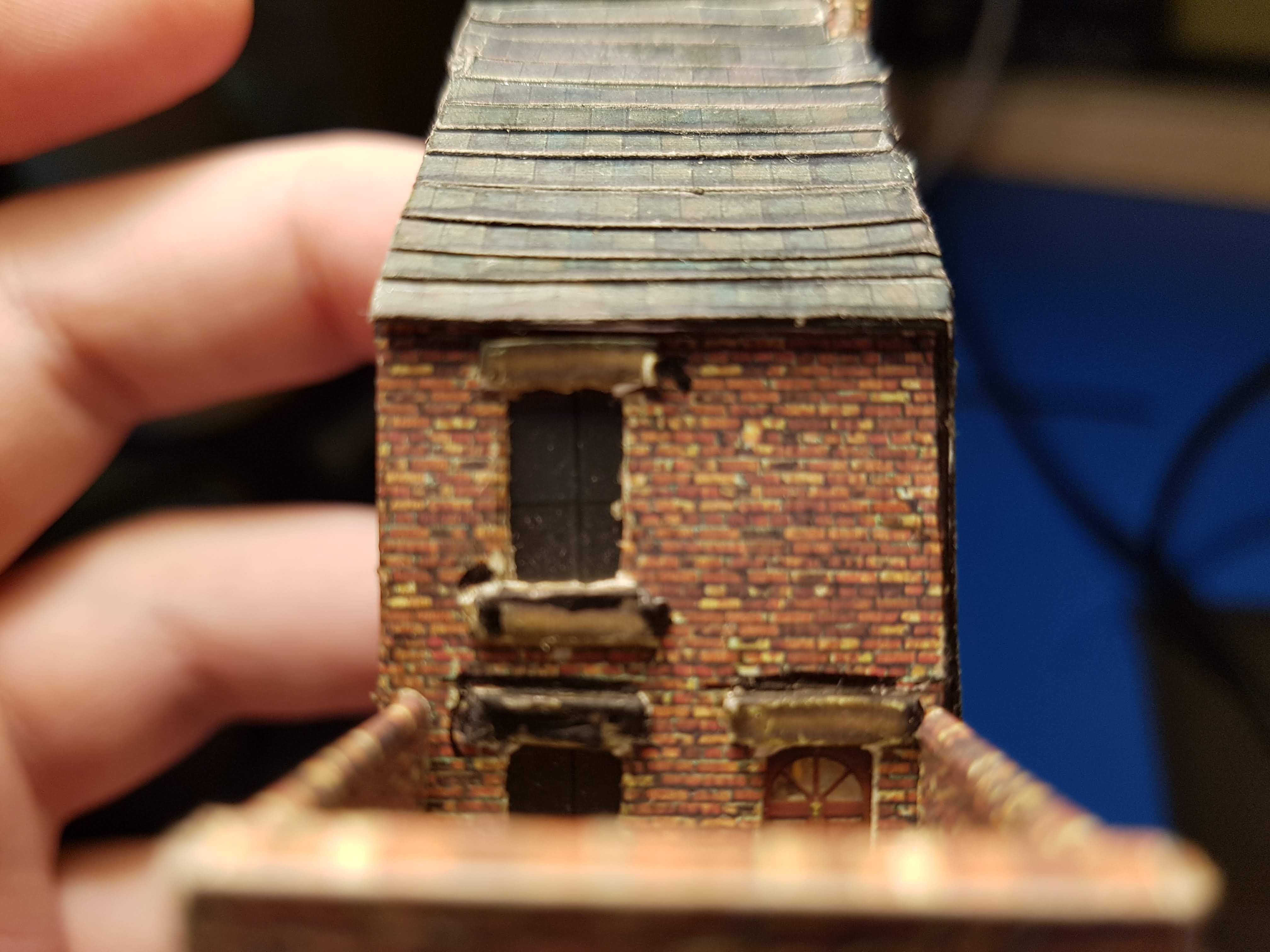
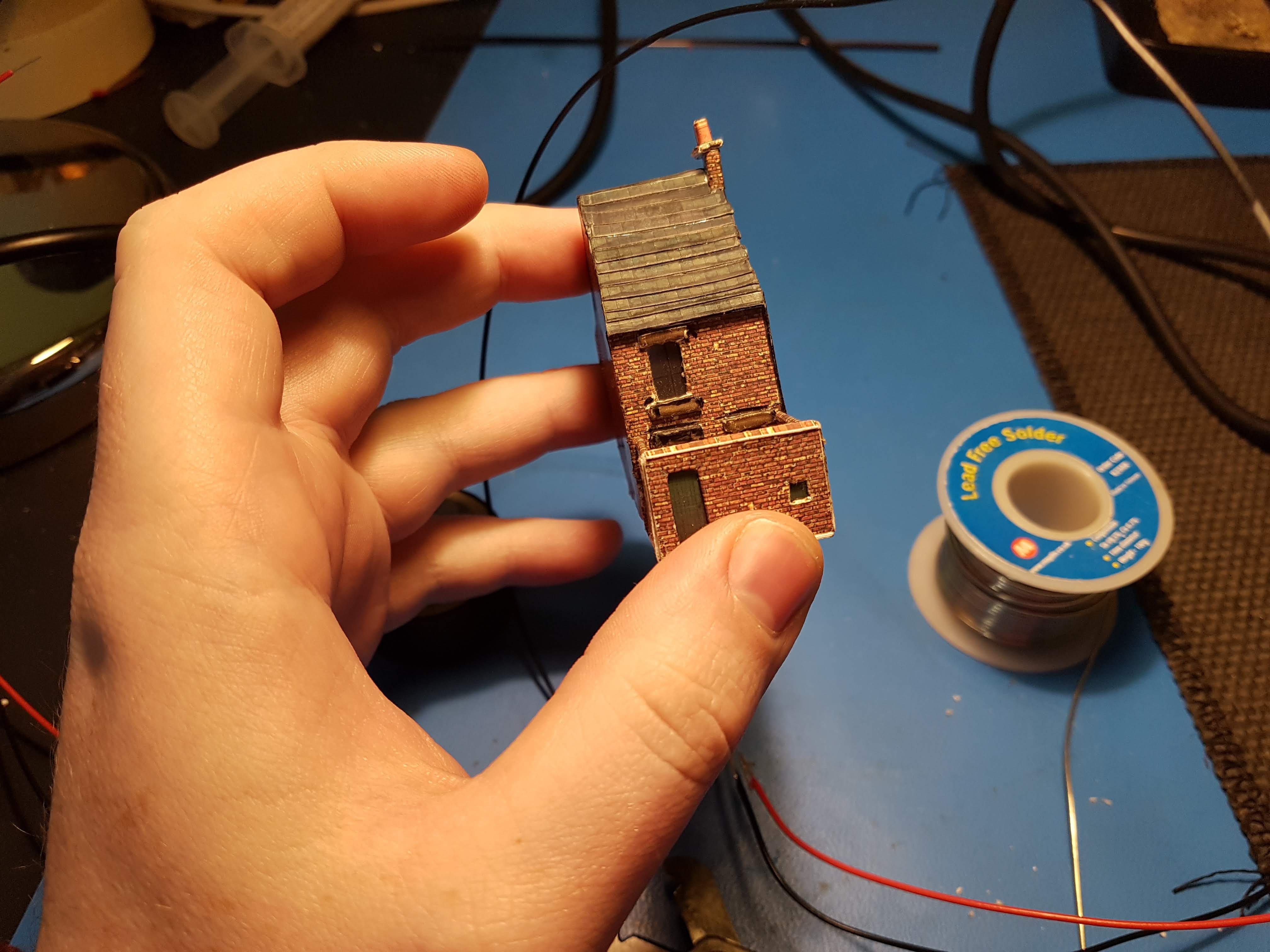
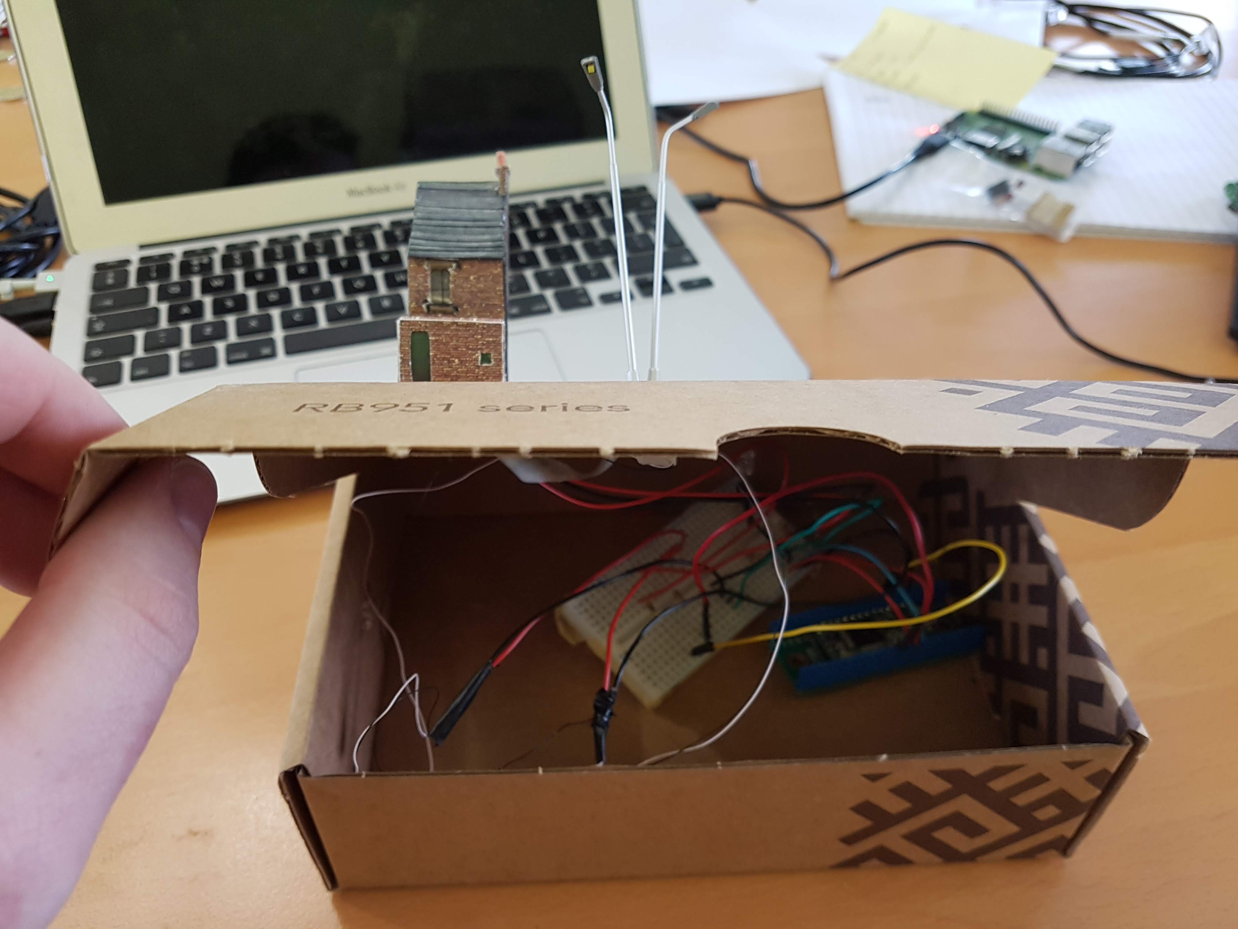
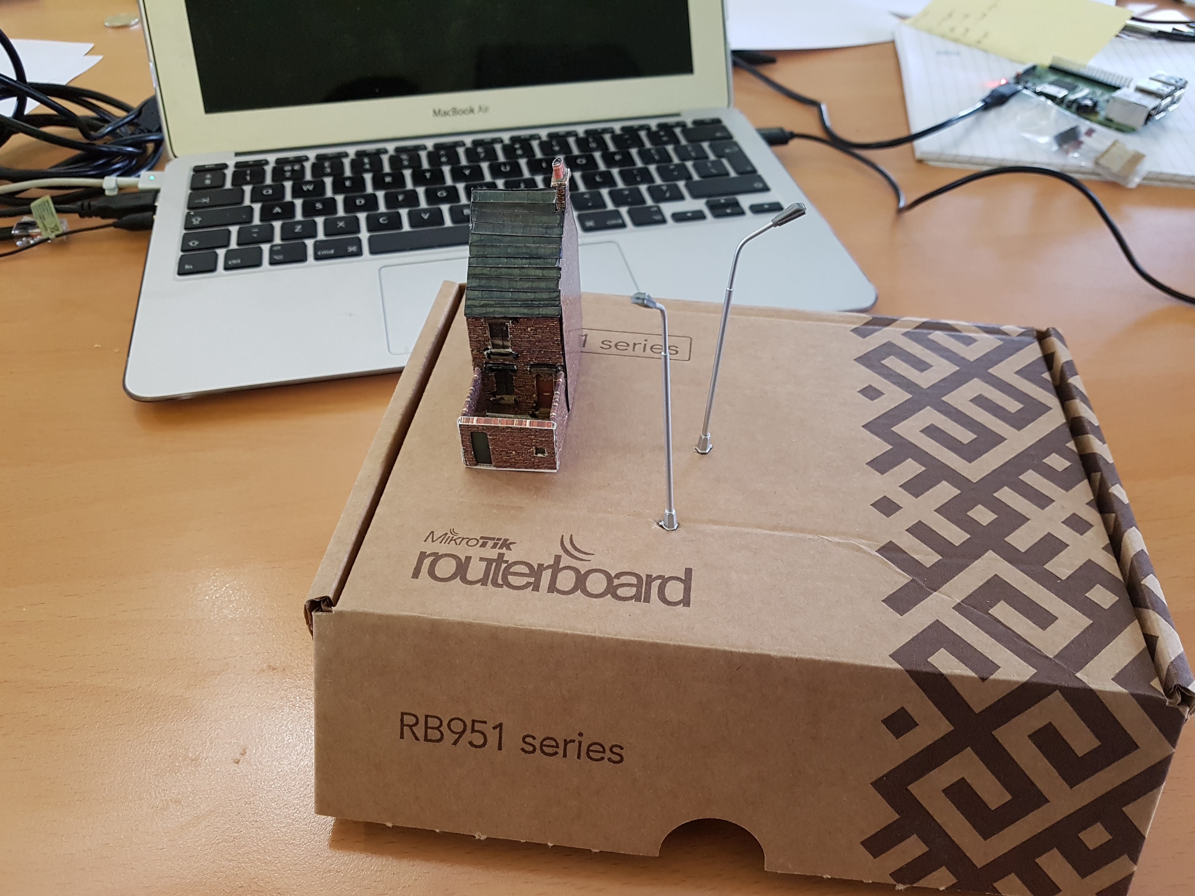
10/22/2018 at 00:07 • 0 commentsUsing Smart Models printable building kits, I have created a few test buildings for the project, one early attempt was used for testing with the LED lighting, these paper-craft buildings in N Scale are really small to work with and a few things learned on early builds were that cutting out with a craft knife has to be precise, straight cuts on the line are vital (had to get a pair of reading glasses from the pound shop) Also glue gets everywhere (maybe just me) accurate gluing with minimum glue is required. Tweezers, magnifier and toothpicks are handy tools to have around.
![]()
![]()
![]()
![]()
Oh yeah bought some sheep from China too.
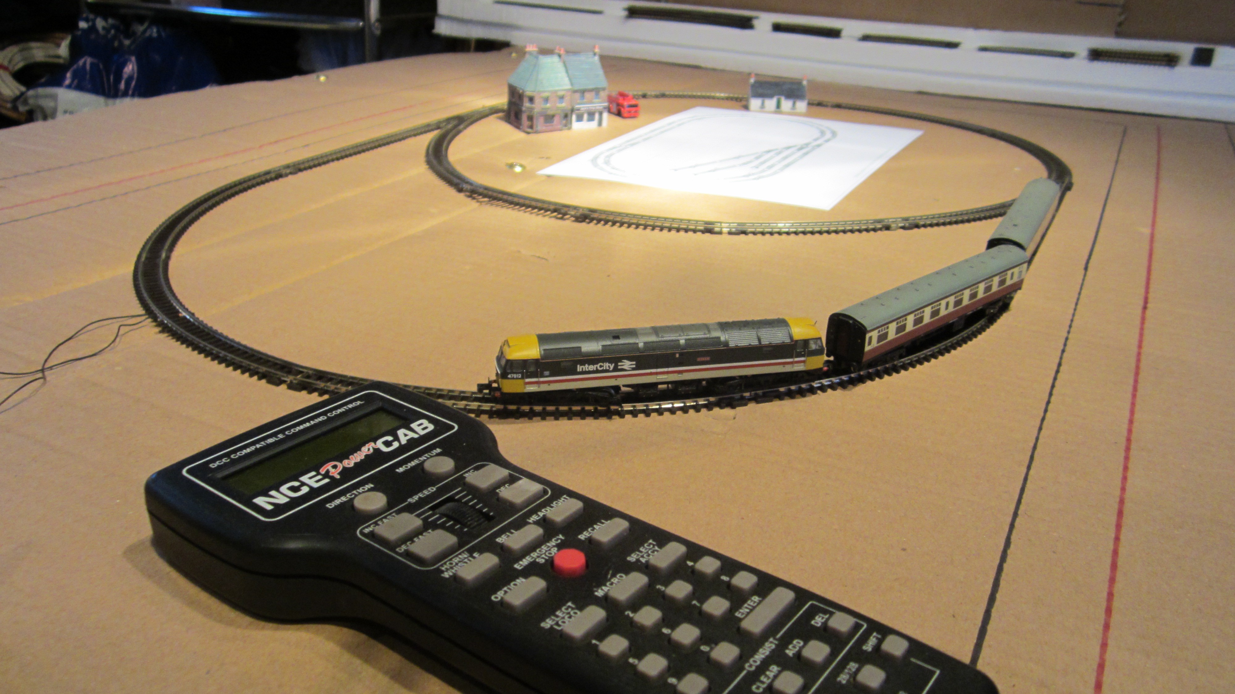
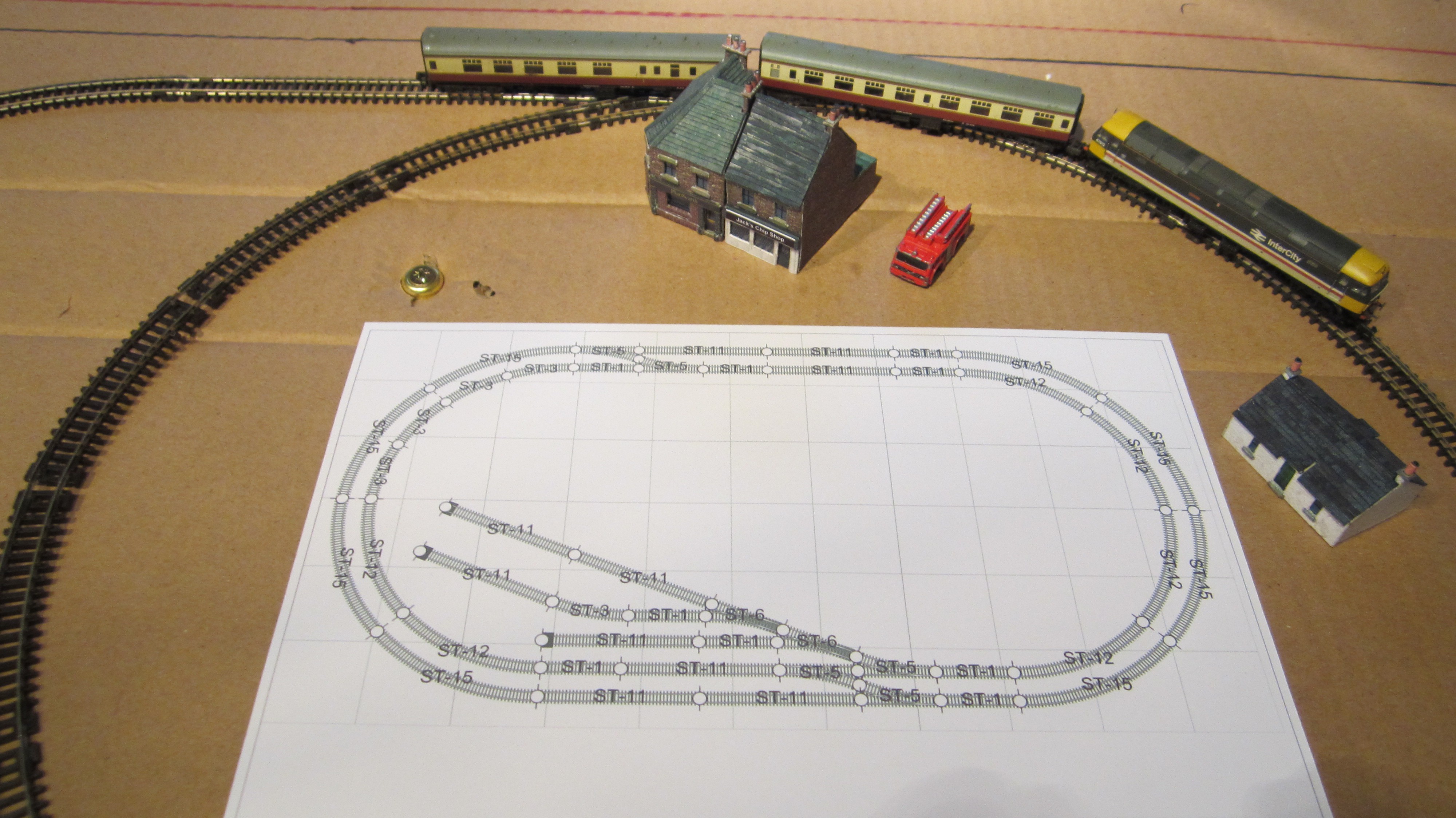
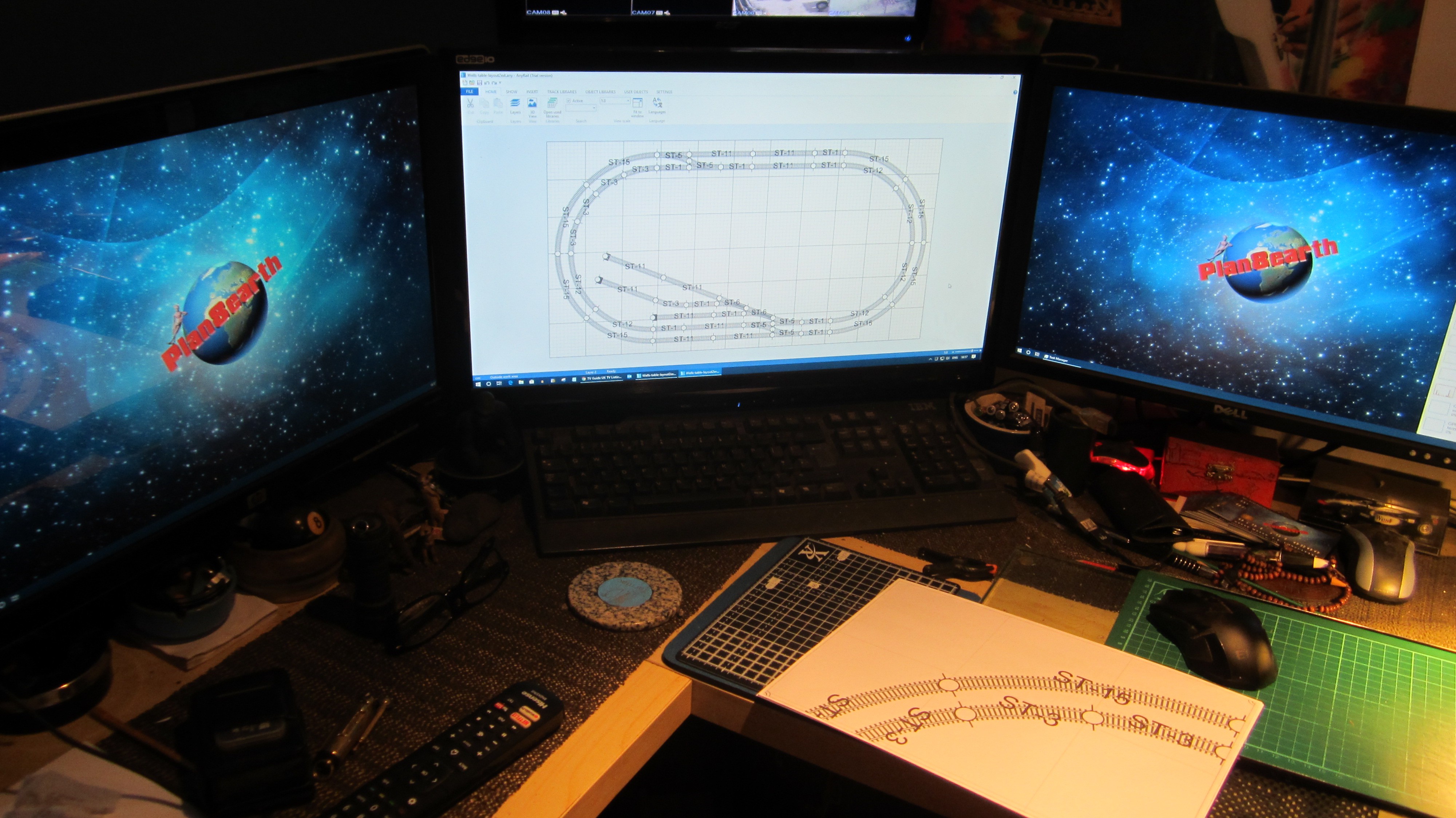
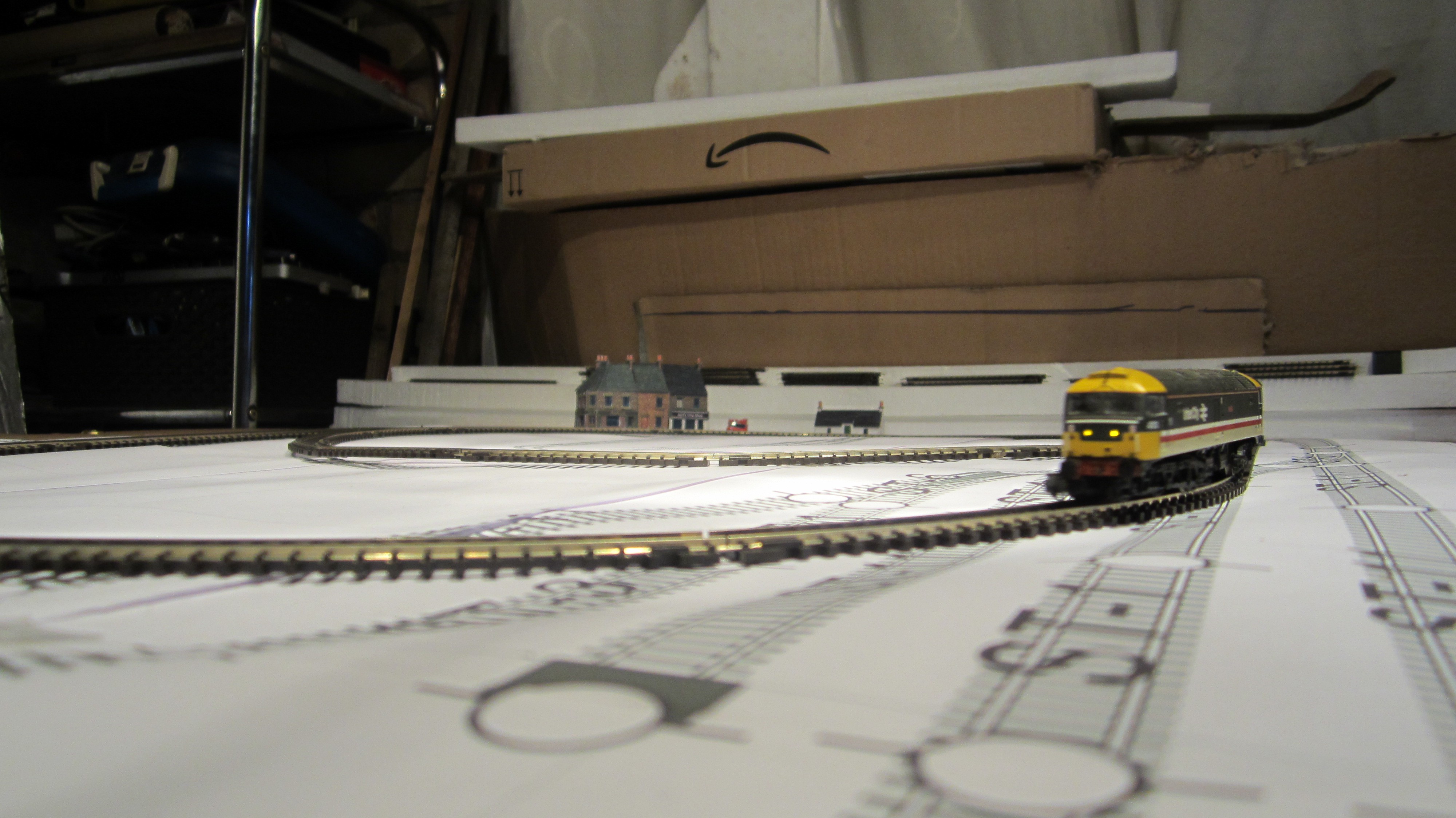
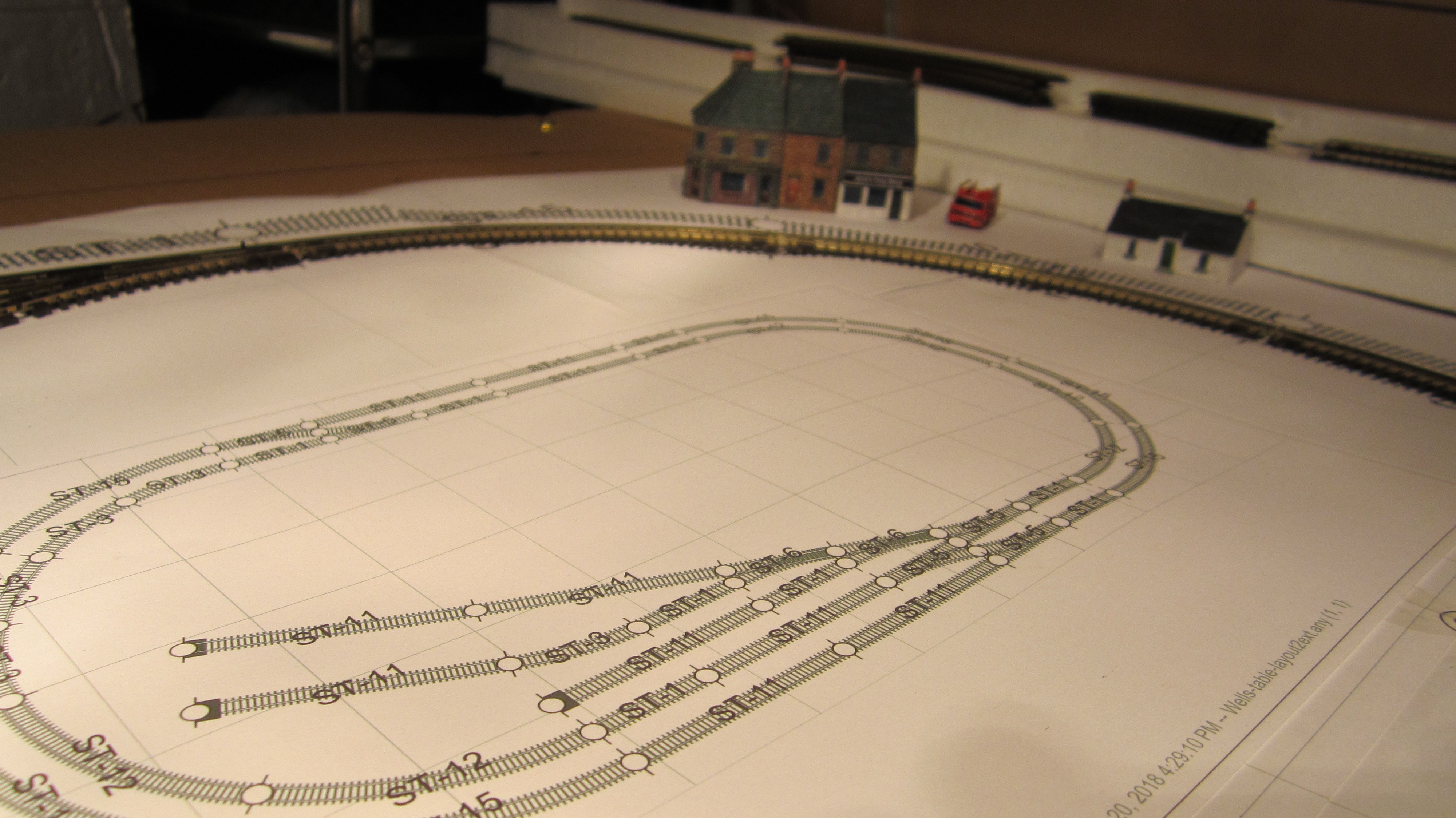
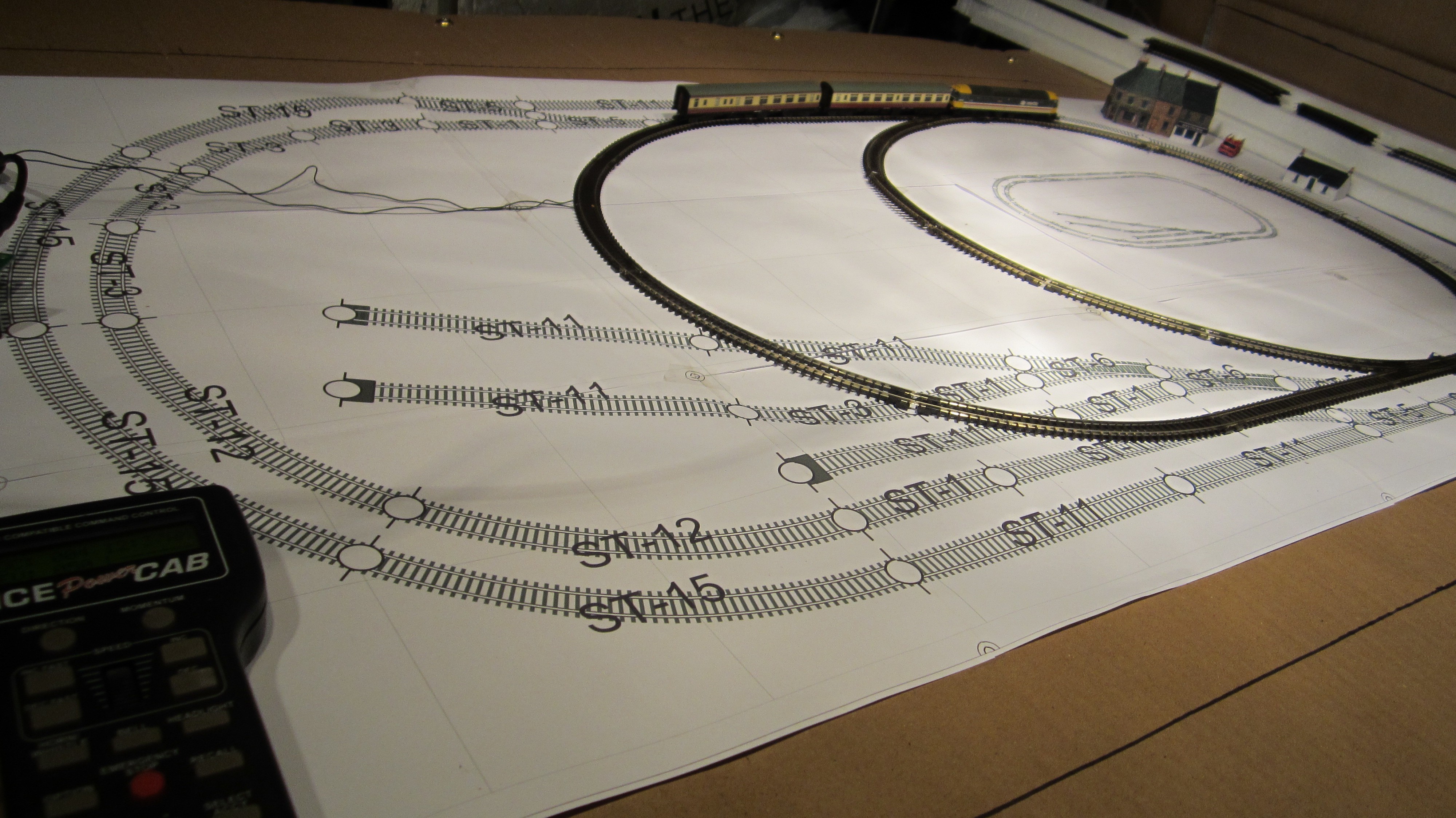
Needless to say I have got better at paper-craft and planning on doing a small village scene, but first the track layout is next on the list. First of all the dimensions are somewhat dictated by the glass top which is 1100 mm by 600 mm. We used a trial version of layout planning software AnyRail to come up with a layout that is simple but has enough interest with two trains running simultaneously. This turns out to be more of a challenge than meets the eye if we want to automate the running with manual override capabilities.
![]()
![]()
![]()
![]()
![]()
![]()
We have some track in the workshop but not enough for what we have planned, we will need to hit amazon or eBay at some point but for now we have printed out a full scale plan of the track layout allowing us to consider the table construction and the scenery construction.
-
Raspberry Pi - Sprog - DCC Train Control
10/17/2018 at 08:16 • 0 commentsThe model train world has moved far forward from the old-school days of analogue current motor control. It's now possible to have multiple trains on a track with sound effects, lights, and motors, and control these trains with ease. DCC (Digital Command Control) is the cool new way to do this. It's a command protocol on the rail lines that allows for addressing and commanding of individual trains on a shared "network" of rail line. DCC can be thought of as quite similar to an i2c or rs482 communications bus but also supplying power at the same time as data. We're planning to use, likely 3, N-scale locomotives for our train layout that all have DCC decoders built into them. To interface to the DCC decoders on the trains we're using the Sprog 3 Command Station.
Sprog 3
![]()
The Sprog 3 is a simple USB based DCC controller that allows for both programming and running of devices on a DCC rail network. It's a really small packaged device and it works on a simple serial command interface. Traditionally it's connected to a PC or Raspberry Pi running JMRI which is a super powerful program that handles reprogramming of devices, track layouts and automation and a tonne of other stuff; it's actually over powered for what we're looking to do and I'm excited for the opportunity to create my own interface for working with the Sprog. To be fair, another reason we're using this controller is it was repurposed from a previous project so essentially for this project it was free.
DCC Command Protocol
So when it came to working with the Sprog I had a little bit of a harder time than expected. The documentation for the Sprog is reasonable. It has a command list for "rolling roads" and other testing features but these setups tend to be for reprogramming purposes. When it comes to actually running a full working track layout you need the sprog in it's command mode instead.
I needed a way to get a better look at what the command structure should be for the Sprog. I struggled to find anything under "Dcc command list" on google due to an open source "Dcc controller" project that actually led me astray. In frustration I tried a different tactic; I setup JMRI and after a lot of jigger-pokery I managed to get it up and running with my lovely little DCC decoder tester.
![]()
The decoder tester is basically a deconstructed train on a pcb. It has lights, a motor and speaker and with a decoder plugged in it reacts exactly like a train. Using JMRI (which reaffirmed my opinion that it's overly complex) I was able to monitor the packets that JMRI was sending to the Sprog based on my inputs to the JMRI "throttle" control. This made it clear that the Sprog works on a packet format similar to;
< O -Train Address- -Data 1- -Data2- -CheckSum- >
Now I could have simply gone through the process of testing every button press and speed value, creating a look up table of commands and using that to jerry-rig the control I wanted, but obviously it was much better to understand the packet and decode it to allow me to create commands on the fly. I did a couple of easy checks to start out; Speed, Forward, Backward, Stop slow and hard emergency stop. Interestingly these commands were all encoded in one packet. I thought that possibly there would be a separate command for direction and then speed but this didn't turn out to be the case.
![]()
Clearly I needed some documentation to move forward. I contacted the owner of the Sprog site and he replied pointing out that the sprog accepts "standard NMRA DCC commands". That led me down the rabbit hole of eventually finding the NMRA spec sheet for DCC commands. Reading through the document we can see that the DCC commands are based on a packet layout as discovered and use the individual bits in a byte to differentiate the different commands and control. Another point made to me in the email was that JMRI repeatedly sends the same commands over and over again. This makes sense when we consider that the trains my lose packets or even full connection as they move round the rail track. By refreshing the packets consistently we ensure that the train behaves as expected.
It's going to take a lot more work but as of today I have a good set of python code to control an addressed train's speed, direction and one set of lights using the NMRA specs. You can find this code in my git hub under python_scripts. My future work will include supporting the "F" function buttons for the trains and also setting up a method of continually sending packets out at a refresh rate instead of just the once at the moment.
-
Hardware - LEDs & LDRs - Automation Part 1
10/12/2018 at 12:19 • 0 commentsPart of the fun of this build is to put small subtle details into it that add a layer of complexity to create a more "life-like" feel to the miniature layout. With this in mind we've taken our LED lighting for the housing, street lighting, etc and paired them with an LDR - light dependent resistor, or photoresistor. An LDR can be used to measure the level of light around the sensor. For our application this means we can use an LDR to measure the ambient light level in the layout and use that data to turn on LEDs as if the world is reacting to the light around the table. This paired with our dimming LEDs creates a nice result (code block at the end of the post);
![]()
By pairing multiple LDRs with block groups of LEDs then I'm hoping we can create localised areas that will react to objects placed on the top of the table that reduce the light in a certain area and the local LEDs turn on in response. Combining this with my house and street light setup we can see a nice little result;
![]()
/* Turns on LEDs based on LDR feedback Uses analogue write to handle dimming of LEDs */ int Redled = 6; int Yelled = 5; int Grnled = 3; boolean RedState, YelState, GrnState = false; int RedRate = 1; int YelRate = 10; int GrnRate = 60; // the setup routine runs once when you press reset: void setup() { // initialize the digital pin as an output. pinMode(Redled, OUTPUT); pinMode(Yelled, OUTPUT); pinMode(Grnled, OUTPUT); pinMode(A5,INPUT); Serial.begin(115200); } // the loop routine runs over and over again forever: void loop() { Serial.print("LDR Value;"); Serial.println(analogRead(A5)); static boolean LightState = true; boolean newLightState = LightState; if(analogRead(A5) < 600) newLightState = true; else newLightState = false; if(LightState != newLightState) { LightState = newLightState; if(newLightState == true) { //Brigthen all leds for (int i = 0; i < 255; i++) { analogWrite(Redled, i); analogWrite(Yelled, i); analogWrite(Grnled, i); delay(10);//reset timer } }else { //Dim all leds for (int i = 0; i < 256; i++) { analogWrite(Redled, 255-i); analogWrite(Yelled, 255-i); analogWrite(Grnled, 255-i); delay(10);//reset timer } } } } -
Hack a glass table top
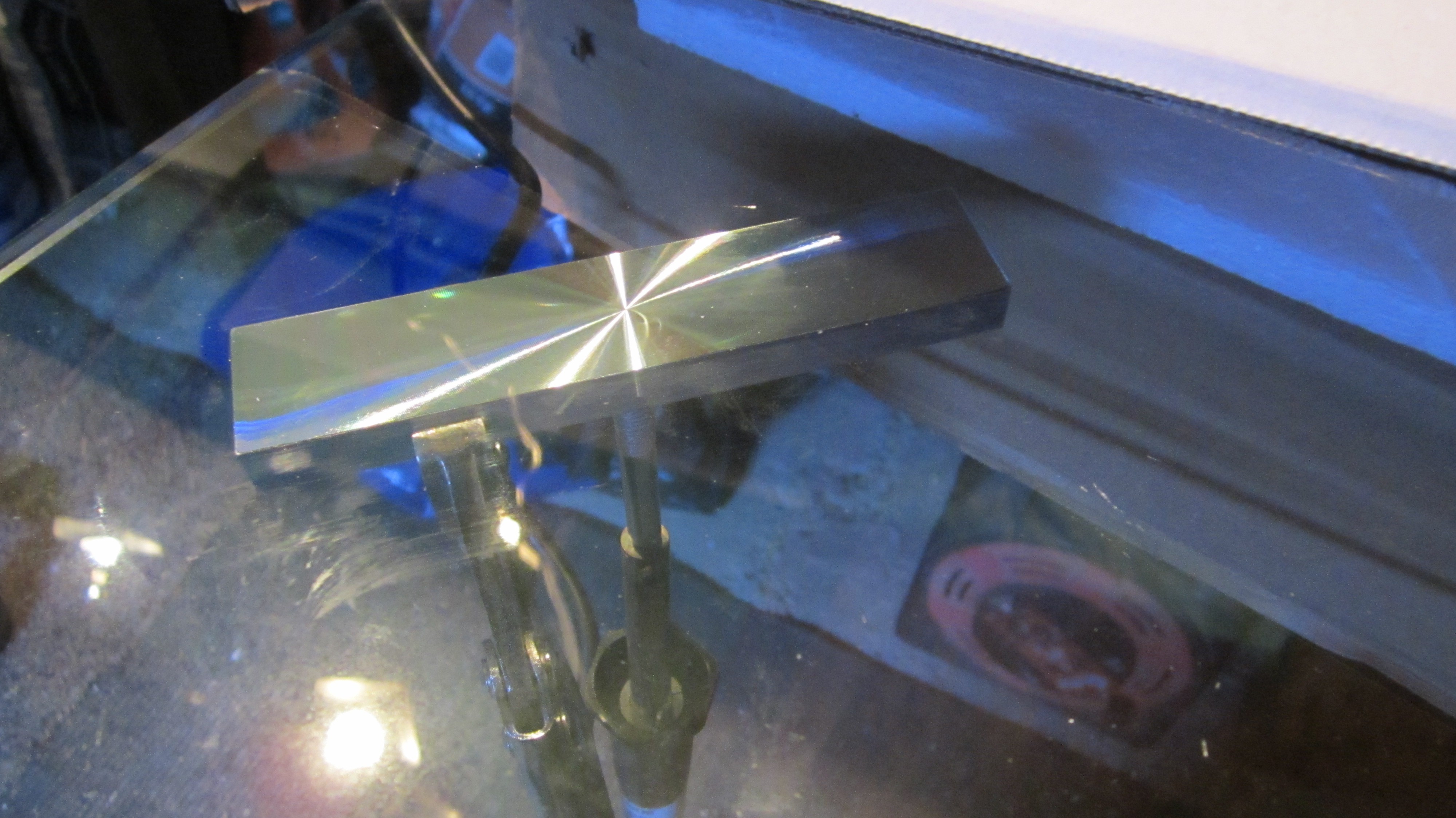
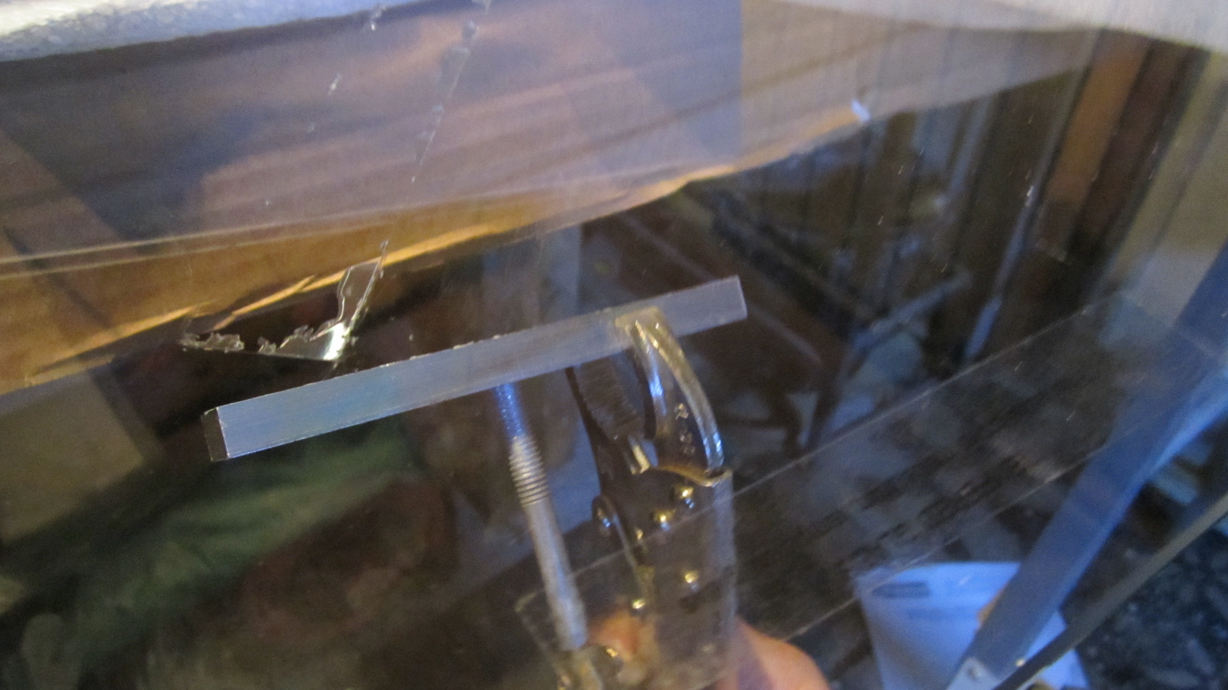
10/12/2018 at 00:37 • 1 commentI bought a £29.99 glass table just for the glass although it had 4 of these metal adaptors glued in place. It was the correct size for the table project and it was tempered and bevelled glass (thought it'd be worth the risk). After a bit of research on the internet, I realised I had to apply enough heat to the adaptor to melt the glue used to attach the adaptor without risking too much heat to the glass.
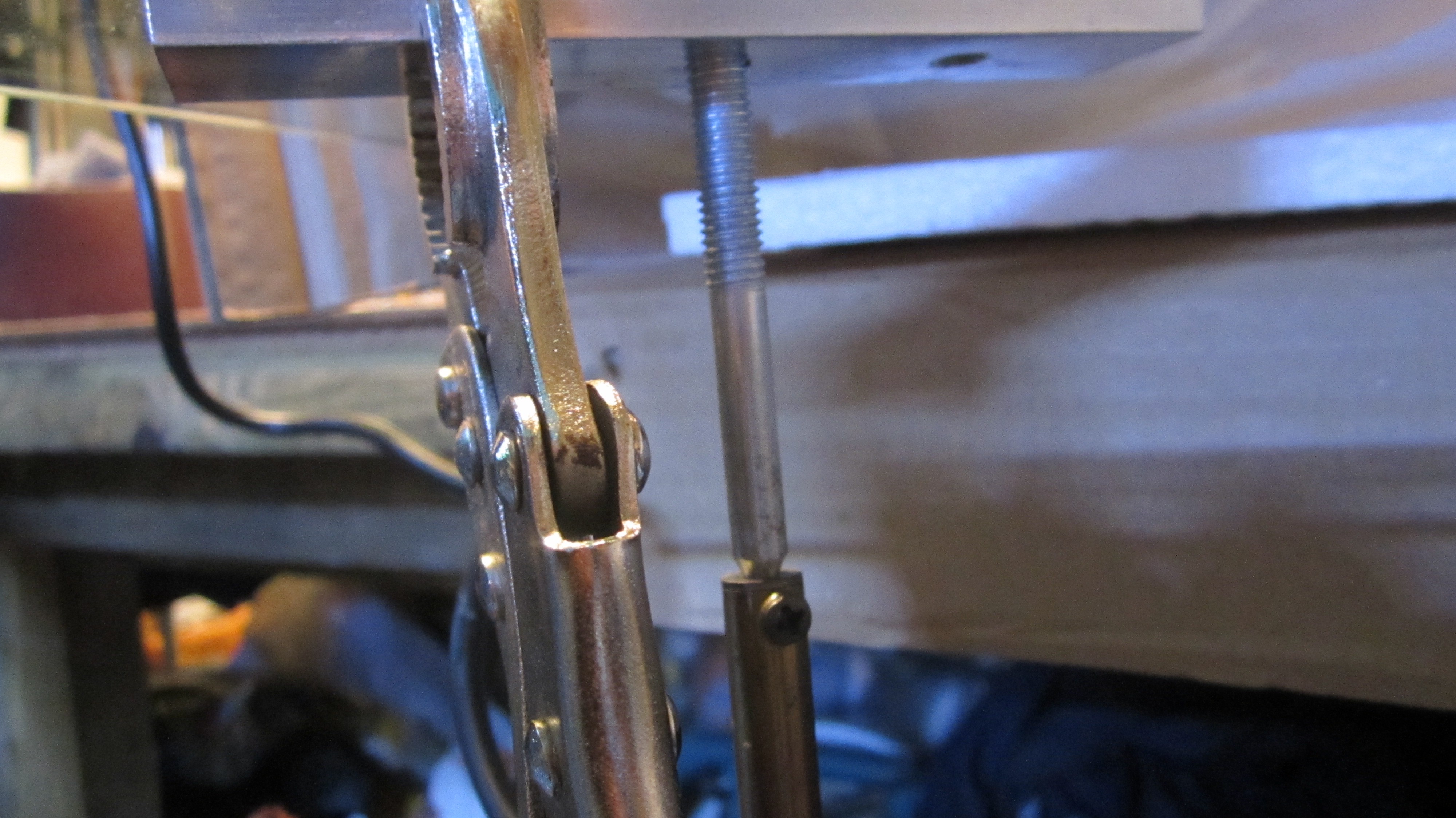
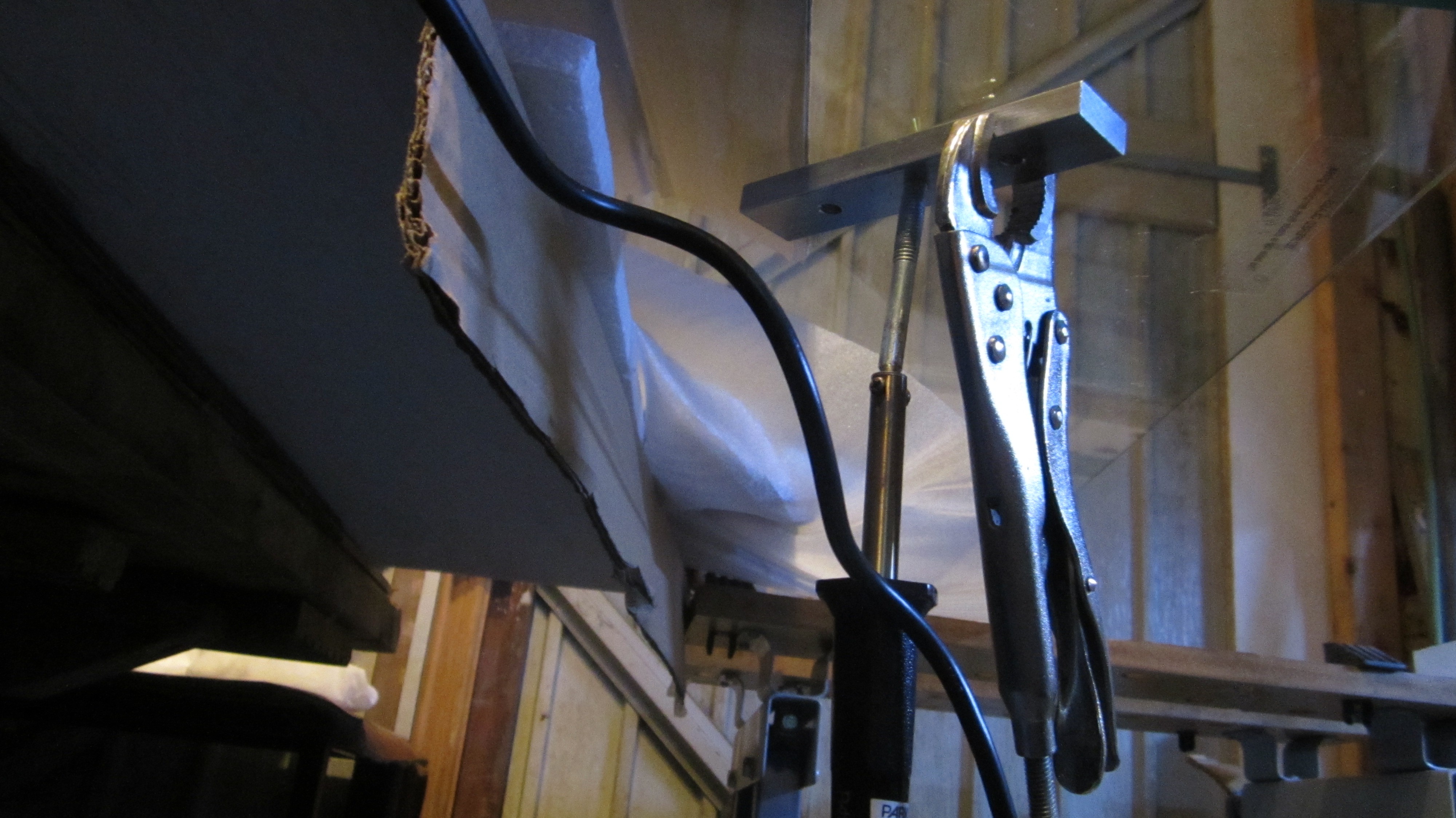
I used a soldering iron and ground down a steel bolt so it would replace the tip and could be also screwed into the metal adaptors and rest there while heating up. While it was heating I clamped some mole grips to the metal and applied a constant downward pressure to it until the glue got to its its melting / softening point (500 degrees?)and it comes away. So no heating of the glass and just enough heat to get it off.
Worked great and we now have a clean piece of bevelled tempered glass for the project.
![]()
While it was heating I clamped some mole grips to the metal and applied a constant downward pressure to it.
![]()
![]()
It took about 40 mins before any signs of softening.
![]()
The bubbles began appearing on the edge and spread across the adaptor.
![]()
Just drops off when soft enough without any damage to the glass, just another three to go!
-
Hardware - LEDs - A digital boy in an imperfect world.
10/11/2018 at 15:39 • 0 commentsI've had a lot of fun playing with the LEDs. As of this moment each LED is connected to a pin on the Teensy. In the future, as the number of LEDs grows, I'll need to use a buffer chip of sorts to prevent running out of pins or over current draw from the Teensy. For the code I've created wrapper modules to make controlling the LEDs easy with the Teensy and they should be upgradable when I change control method.
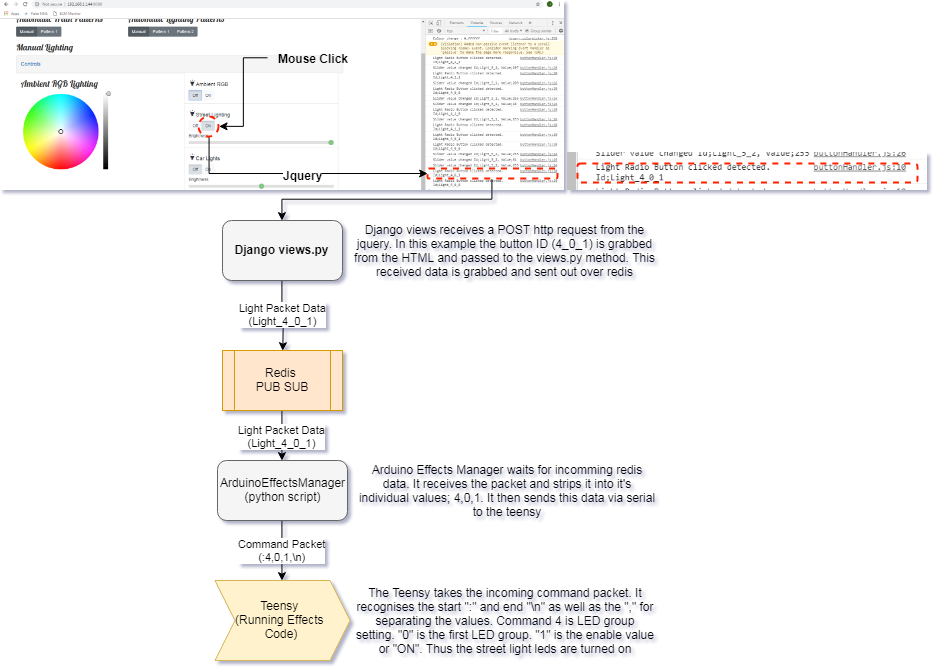
Before writing this log entry I had the LEDs switching on and off as shown in my previous entry. This shows that the logic control for the LEDs is working and we have that instantaneous control. How this is achieved from mouse click to LED "on" is detailed below;
![]()
The Imperfect World
LEDs are a perfect example of a digital device. They are generally on or off without any variation of power in the middle; as soon as you apply a voltage above a threshold you get full brightness depending on the allowed current usage. This is great for fast paced, reactive interfaces; nothing catches your attention like a blinking LED. However in the real world of lighting, particularly older homes and street lights, this on-off flip to full brightness isn't achieved instantaneously. It takes time for normal bulbs to warm up and produce their full brightness, perhaps this isn't ideal in the real world but aesthetically it's comforting and more natural than instant "LIGHT!". With this in mind can our LEDs replicate this imperfect "warm up"?
Trick of the eyes
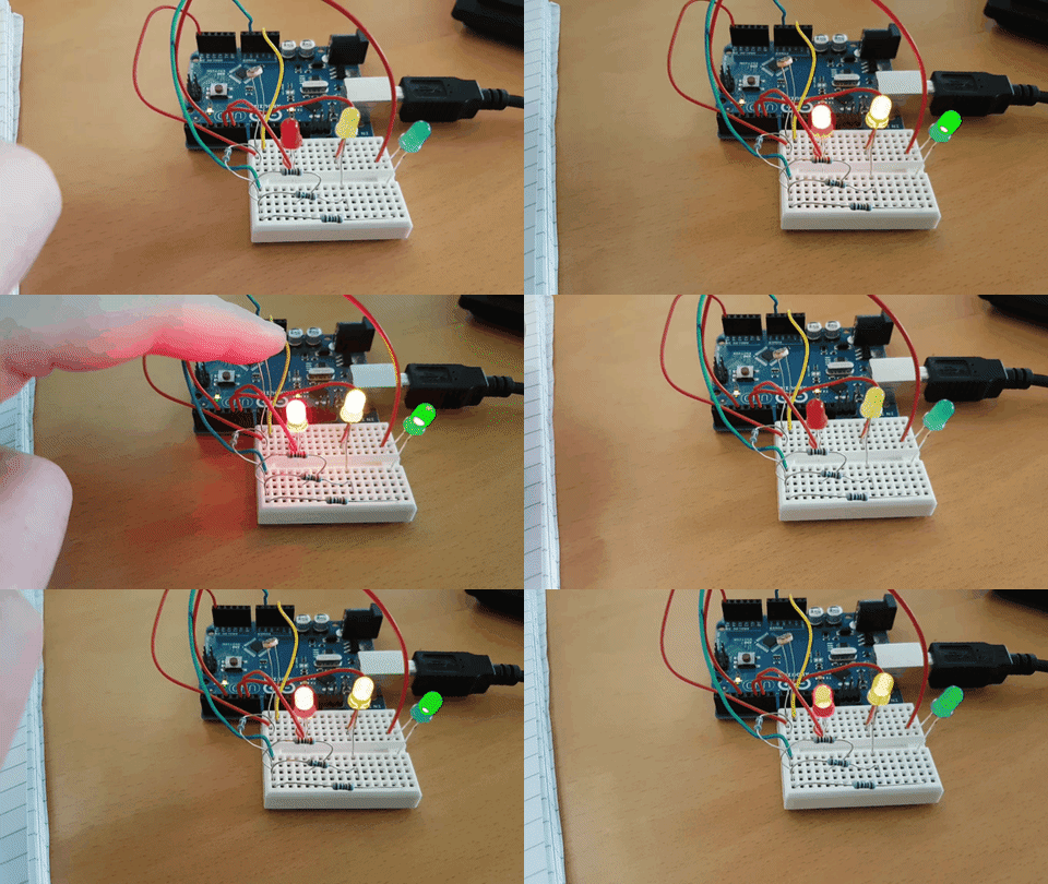
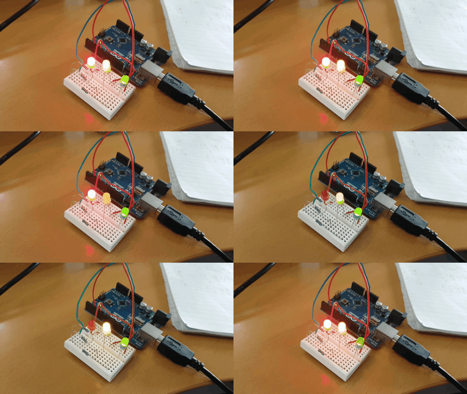
Again, unlike the analogue world of bulbs where we can use a variable resistor (dimmer) to vary our brightness, the digital world of LEDs requires a more complex solution to allow for "dimming". As stated an LED is either on or off, this is fact, but our eyes are easily deceived. Blink an LED above 60 blinks a second and what should be on-off-on-off appears to our eyes as constantly on; this neat little trick can be seen here:
![]()
(red flashing 1/s, yellow 10/s and green 60/s - not as easy to see as the yellow is brighter)
The code to achieve this effect is really simple. We're just turning the LED on and off and on again 60 times a second.
/*
Based on "Blink" example.

Runs 3 LEDs blinking at different rates dependent on timers.

The "on" and "off" period are the same amount of time.
 */

int Redled = 6;
int Yelled = 5;
int Grnled = 3;

boolean RedState, YelState, GrnState = false;

int RedRate = 1;
int YelRate = 10;
int GrnRate = 60;

// the setup routine runs once when you press reset:
void setup() {
  // initialize the digital pin as an output.
  pinMode(Redled, OUTPUT);
  pinMode(Yelled, OUTPUT);
  pinMode(Grnled, OUTPUT);
  Serial.begin(115200);
}

// the loop routine runs over and over again forever:
void loop() {

  static unsigned long RedTimer = millis();
  static unsigned long GrnTimer = millis();
  static unsigned long YelTimer = millis();

  //Timer for red led
  if(millis() - RedTimer > 1000/(RedRate*2))
  {
    RedState = !RedState; //Flip value of RedState
    digitalWrite(Redled, RedState); //Write to pin
    RedTimer = millis(); //reset timer
  }

  //Timer for Yellow led
  if(millis() - YelTimer > 1000/(YelRate*2))
  {
    YelState = !YelState; //Flip value of YelState
    digitalWrite(Yelled, YelState); //Write to pin
    YelTimer = millis(); //reset timer
  }

  //Timer for Green led
  if(millis() - GrnTimer > 1000/(GrnRate*2)) //need to double the rate as this covers "on" and "off" cycle
  {
    GrnState = !GrnState; //Flip value of RedState
    digitalWrite(Grnled, GrnState); //Write to pin
    GrnTimer = millis(); //reset timer
  }
}
Dimming by PWM
So blinking really fast allows us to trick the eyes into seeing a constantly "on" LED but we still don't have control over the brightness. The answer lies in "PWM" - Pulse Width Modulation. We're basically taking the "blinking-really-fast" trick and adding another layer on top. Previously when we were blinking the LED we had the same amount of "on" and "off" time. This is known as a 50% duty cycle where the pin spends the same number of milliseconds off as it does on. By varying the duty cycle we can create uneven amounts of "on" and "off" time and this gives us our brightness control; 10% duty cycle means the pin is only on for 10% of the time creating a dimmer light, while a 90% duty cycle creates a much brighter light by having the pin on 90% of the time. By design microcontrollers have this duty cycle method of pin control , PWM, as a standard feature and the Arduino makes this really easy to use. The standard PWM module of an Arduino runs at around 1kHz so we're well above our 60 blinks a second and by selecting the PWM capable pins (marked on an Arduino with "~") we can use the analogWrite method to control the brightness of our LED. Varying the analogWrite value varies the brightness and bringing it all together we can create our nice "warm up" effect with the lighting in our project.
![]()
(oof that gif did not compress well)
//************************************* Uses the same setup from before // the loop routine runs over and over again forever: void loop() { //Brigthen red led for (int i = 0; i < 255; i++) { analogWrite(Redled, i); delay(10);//reset timer } delay(500); //Dim red led for (int i = 0; i < 255; i++) { analogWrite(Redled, 255-i); delay(10);//reset timer } //Brigthen all leds for (int i = 0; i < 255; i++) { analogWrite(Redled, i); analogWrite(Yelled, i); analogWrite(Grnled, i); delay(10);//reset timer } delay(500); //Dim all leds for (int i = 0; i < 255; i++) { analogWrite(Redled, 255-i); analogWrite(Yelled, 255-i); analogWrite(Grnled, 255-i); delay(10);//reset timer } } -
Hardware - LED Testing - Little blinkies are fun!
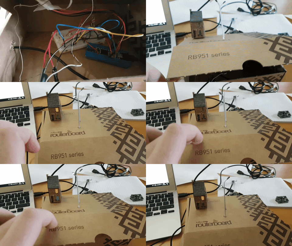
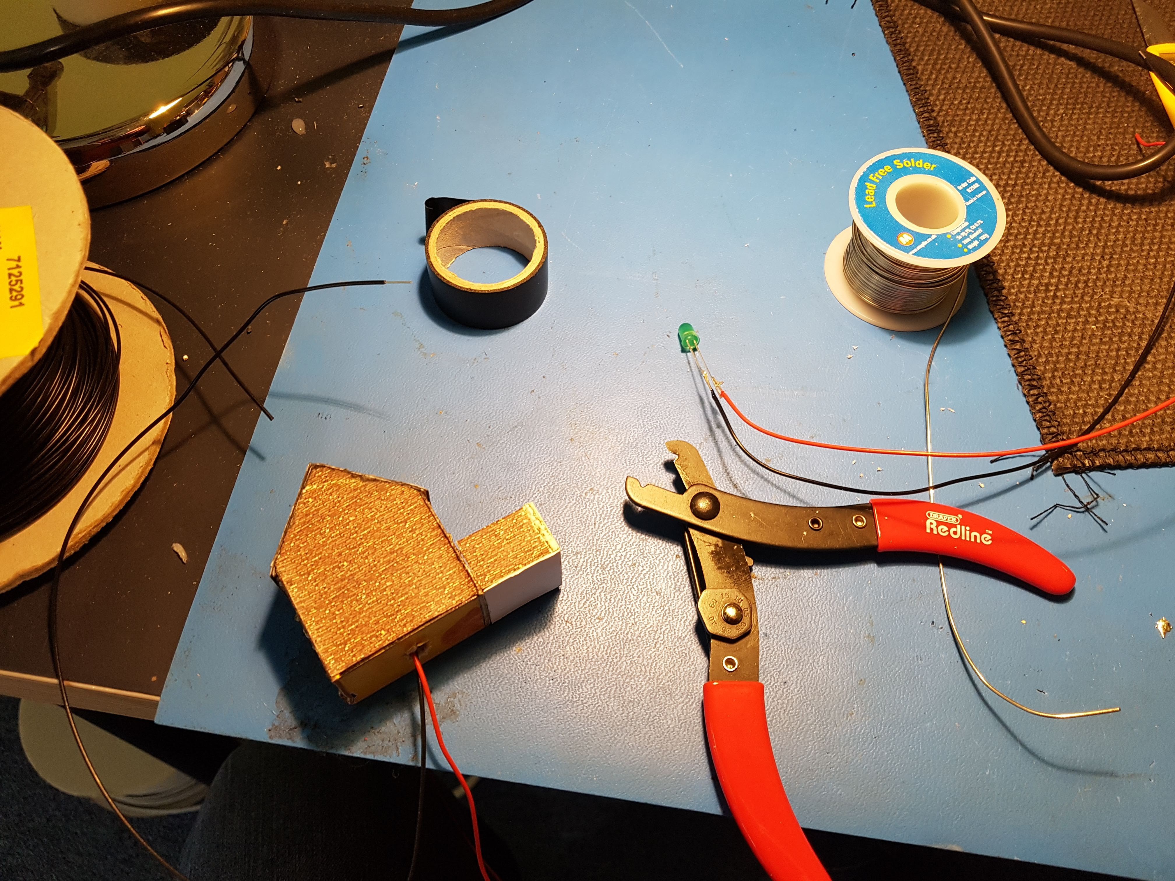
10/09/2018 at 14:33 • 0 commentsPutting LEDs inside something instantly increases its cool factor by 50%. What started as a miniature house that would forever sit lifeless on the layout is now more alive simply by adding some LEDs to liven up the place. The cool thing about these miniature N-Scale (which is tiny by the way!) buildings is that they've been built with acetate clear windows and internal floors. That means when I put 2 LEDs into the house then I can individually light up the top floor and the bottom separately. It's a nice touch and you can see the effect in the video below.
![]()
![]()
![]()
![]()
![]()
![]()
-
Python Anywhere - Django - Git - Online Test Site
10/09/2018 at 10:39 • 0 commentsWhilst working on any project it's always beneficial to get outside feedback. I'm working with my Dad on this one so we've talked a lot back and forth over the phone but sometimes it's just easier to "show" what I mean rather than tell. With this in mind I set about using the previous Django Girls Tutorial to "Deploy" my site online and create a mock up that could be viewed and interacted with without the risk of opening up my Raspberry Pi to the world wide web.
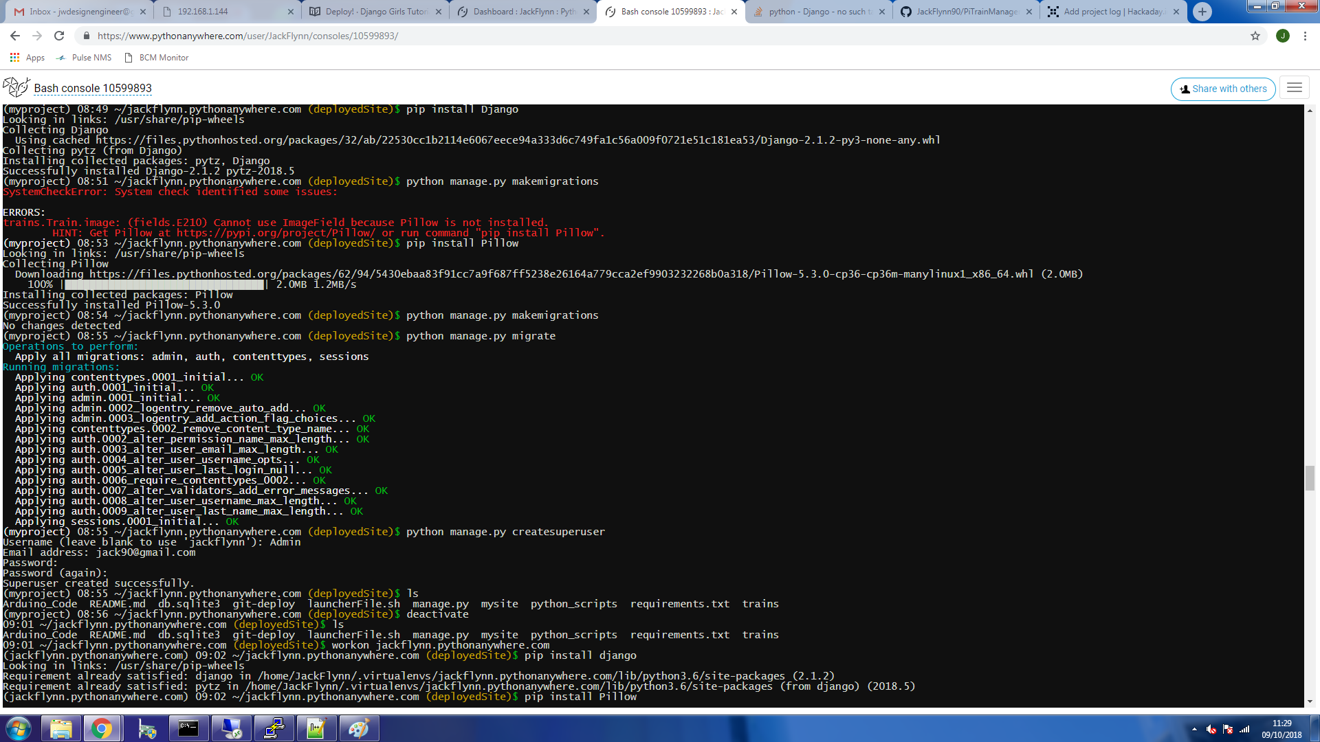
Hosting a Django site online is essentially done by using Git to store the working files online and then passing those files to a second web server that will host the site. Python Anywhere was recommended by the tutorial and was simple enough to get setup. It runs very similar to a shell interface like working with the raspberry pi but inside your browser;
![]()
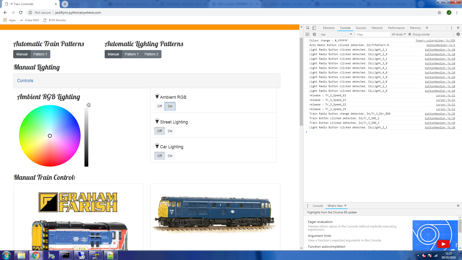
You can find the mock up of my site here. Whilst on the site if you open up the browser development tools then you can monitor the console for the debug statements coming from my java script. This lets us view how the html buttons are parsed by the javascript and what is being sent via "POST" to Django.
![]()
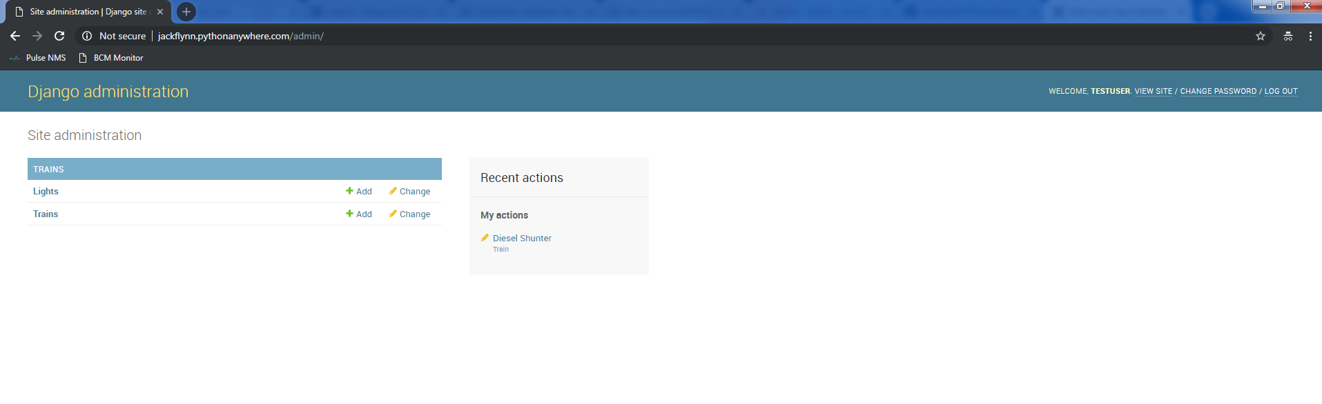
A final little piece I added to the site was to create a basic user for the Django admin panel. This user has the ability to add and edit the database entries for the "Trains" and "Lights" tables. If you want to play around with it then you can go to - http://jackflynn.pythonanywhere.com/admin/ - and then use the following log in details;
User - TestUser
Password - coffeetable1
![]()
Once logged in you can then change the entries in the tables or add new entries. The main page will update on a refresh and you can see for yourself how Django actively generates the html based on the database.
-
Raspberry Pi - Bash - A hard job & a lazy man
10/03/2018 at 13:28 • 0 commentsAfter detailing the code flow for the Raspberry Pi and getting some initial scripts working with Redis and my Teensy, I realised that I was having to launch 3 different objects manually in order to get everything working. I had to run Django via the manage.py to get the site up, then open another terminal and run Redis for passing data between my scripts and finally to get the Teensy communication working I had to run the "ArduinoEffectsManager" script. An added step was also that I had to launch my virtual environment before running my python scripts.
While debugging this was really useful as I could track the printed outputs from my scripts but for a quick demo it wasn't ideal. There's a quote that goes around; "Whenever there is a hard job to be done I assign it to a lazy man; he is sure to find an easy way of doing it.". I decided to be lazy and find a nicer way to get everything running as eventually I would need everything running without my input anyway and it had me learn a bit more about running tasks on linux.
---------- more ----------For setting up Redis I followed this guide here. There were a couple of issues to begin with but I got it working and it's easy enough to follow so now Redis is running on boot of the Pi without any input from me.
For the rest of the code the main goal was to get a "launcher" script that I could call upon to get everything running the way I wanted. I've used a tiny bit of shell commands so I knew I could write a shell script to do this. I tested the following;
#!/bin/sh
python ArduinoEffectsManager.py
Which worked for launching the Arduino Effects Manager(AEM). However, this literally ran the script in my terminal and caused me to again see the debug outputs from the AEM. The script also stopped when I closed my terminal. I need to disassociated the call to my terminal to prevent the script from stopping when I close and I also needed to run it in the background to hide the debug output. It's a common enough issue and solved with nohup and the "&";
nohup ArduinoEffectsManager.py &So now my python script is running in the background when I launch my shell script. The "print" debug calls from the script are stored in a separate file under "nohup.out" for the script. Except this didn't work for Django! This was because my shell script wasn't calling my python code from my virtual environment so Django was missing dependencies.
It turned out that to get my virtual environment working I needed to go a step above shell and create a full 'bash' script in order to support the "source" call. A little bit of jiggery-pokery and testing and my final script ended up like this;
#!/bin/bash
set -x #echo on
cd ~ #go to pi root
cd /share/djangoTrain #go to our shared development folder
source myvenv/bin/activate #activate the virtual environement
nohup python manage.py runserver 0:8080 & #run django in backround
cd python_scripts # move to python scripts store
nohup python ArduinoEffectsManager.py & #run our manager script
Now I can call my "launcher.sh" script via bash and I get the following output;
pi@rasppijack:/share/djangoTrain $ bash launcherFile.sh
+ cd /home/pi
+ cd /share/djangoTrain
+ source myvenv/bin/activate
++ deactivate nondestructive
++ '[' -n '' ']'
++ '[' -n '' ']'
++ '[' -n /bin/bash -o -n '' ']'
++ hash -r
++ '[' -n '' ']'
++ unset VIRTUAL_ENV
++ '[' '!' nondestructive = nondestructive ']'
++ VIRTUAL_ENV=/share/djangoTrain/myvenv
++ export VIRTUAL_ENV
++ _OLD_VIRTUAL_PATH=/usr/local/sbin:/usr/local/bin:/usr/sbin:/usr/bin:/sbin:/bin:/usr/local/games:/usr/games
++ PATH=/share/djangoTrain/myvenv/bin:/usr/local/sbin:/usr/local/bin:/usr/sbin:/usr/bin:/sbin:/bin:/usr/local/games:/usr/games
++ export PATH
++ '[' -n '' ']'
++ '[' -z '' ']'
++ _OLD_VIRTUAL_PS1=
++ '[' 'x(myvenv) ' '!=' x ']'
++ PS1='(myvenv) '
++ export PS1
++ '[' -n /bin/bash -o -n '' ']'
++ hash -r
+ cd python_scripts
+ nohup python manage.py runserver 0:8080
+ nohup python ArduinoEffectsManager.py
nohup: appending output to 'nohup.out'
nohup: appending output to 'nohup.out'
Now my site is running and so is the AEM!
"Stop the presses!"
But how do I know they're running? And how do we stop the scripts if we want to change something? Well that's also easy enough with "ps agx". This command shows every process currently running on the Pi (equivalent to Windows Taskmanager).
pi@rasppijack:/share/djangoTrain $ ps agx
(...Hidden stuff, its a big output)
11901 ?        I      0:00 [kworker/u8:0]
12183 ?        S      0:01 /usr/sbin/smbd
12215 ?        I      0:00 [kworker/1:0]
12426 pts/0    S      0:03 python manage.py runserver 0:8080
12427 pts/0    R      0:12 python ArduinoEffectsManager.py
12431 pts/0    Sl     0:04 /share/djangoTrain/myvenv/bin/python manage.py runserver 0:8080
12451 pts/0    R+     0:00 ps agx
We can now see the scripts are running and each has an associated PID which we can use to close the script.
pi@rasppijack:/share/djangoTrain $sudo kill 12427Through a "sudo kill" command we can close the script down and then it's ready for editing and re-running.
A little bit of work for today but it'll save repeatedly opening terminals and running individual scripts. It's nice that we can easily access the scripts debug print outputs via the "nohup.out" files so even if something runs strange we can quickly check the file and see what happened.
-
Raspberry Pi - Development - Project Code Flow
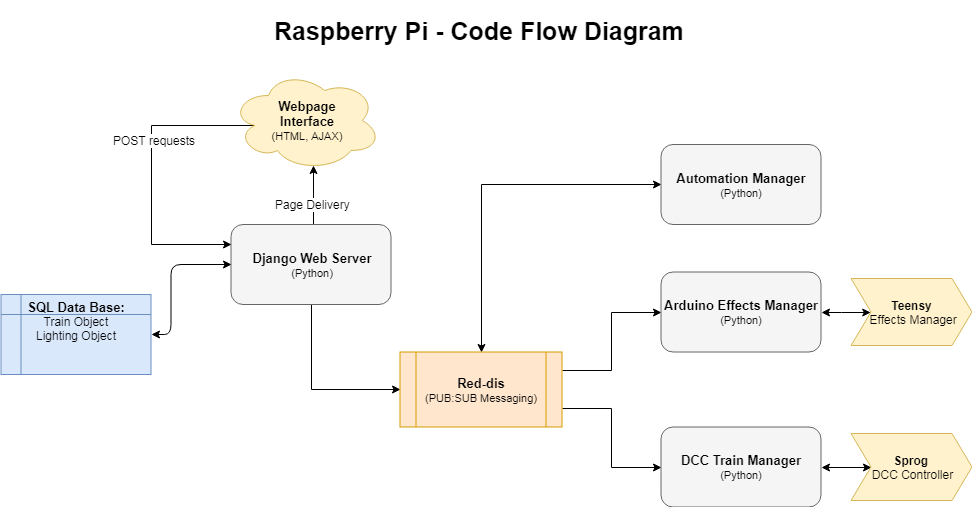
10/03/2018 at 09:16 • 0 commentsDevelopment on the Raspberry Pi is all setup and running smoothly. To better understand what the Pi is doing I've created a rough flow diagram for how it's going to work.
![]()
Starting at the---------- more ----------
Webpage Interface
The webpage interface will be more refined as we dial in the usability and technical requirements. Currently (more posts to follow) the site is running using bootstrap for styling and a couple of jquery pieces that allow for button presses and colour picking for the RGB ambient lighting. The jquery are grabbing the response from the inputs and passing them via post requests to Django.
Django Web Server
The Django web server has mostly been covered in a previous post. This nice bit of python is used to handle the data base which stores the effects objects and also display our web page interface. On receiving the post requests from the jquery elements in the site it then passes these commands to Redis using a publish method.
Redis
Although very powerful and with plenty of uses, I am using Red-dis for it's MQ - publish:subscribe - handling which allows me to pass messages between my python scripts. I used this guide by John Grant as a helper for sorting out my python logic for passing the messages from Django to my Manager scripts.
Automation Manager
I haven't given this any further thought other than I want to be able to create automation within the system that could handle effects like lightning change based on time, timetable for train movements and any other cool ideas that come to mind. The most likely way to do this is to have a standalone script that outputs the required messages over Redis.
Arduino Effects Manager
The script subscribes to the messages from Django via Redis, parses these messages for valid commands and then outputs the data to the Teensy/Arduino to create the lightning and other effects. Serial debugging data from the Teensy is also picked up for use as needed.
DCC Train Manager
Much the same as the Arduino Effects Manager, the script subscribes to the messages from Django via Redis, parses these messages for valid commands and then outputs the data to the Sprog to create the lightning and other effects. Data feedback from the sprog may be useful depending on how the application grows.
-
Raspberry Pi - Development - IDE; Speed, Security, Complexity and Price.
10/02/2018 at 09:44 • 0 commentsFast, Easy, Secure, Cheap. We'd like all 4 but in all engineering disciplines we quickly learn that with the real world there comes trade offs. I wanted an nice IDE interface for developing code on the raspberry pi while it was running in a headless configuration; no screen attached. Looking online there were a number of IDE options that ranged from eclipse; running on my PC with it's various complex setup methods and paid-for plugins, to VIM; an old school text editor that could be run directly on the Pi via a terminal interface. I wasn't a fan of either of these options.
I wanted something that would let me edit files in a clean windows environment that didn't take 2 hours to setup and could come crashing down at any moment. I was willing to compromise on security in return for a free solution as my Pi won't be exposed to the outside world.
Luckily I came across...---------- more ----------
Raspberry Pi File Sharing
The samba file sharing method creates a local directory on the raspberry pi that I can access over my home network with any of my PCs and create, edit or delete files directly. I followed the setup using this guide.
So now I can access my directories, html, python scripts and anything else within the directory of the Pi from any of my local PCs with an added login step for security. I even mapped the IP address of the Pi to a shared drive in windows to make it even easier to access;
![]()
Not everyone would be comfortable exposing the file system on the Pi for development. While I have it setup to require a log-in before accessing files, I'm sure there's a number of reasons not to do professional development this way. For my criteria this fits nicely and it was quick and easy to setup. It also means when I take the Pi home from the office I don't have a complex IDE setup process to repeat on my home PC.
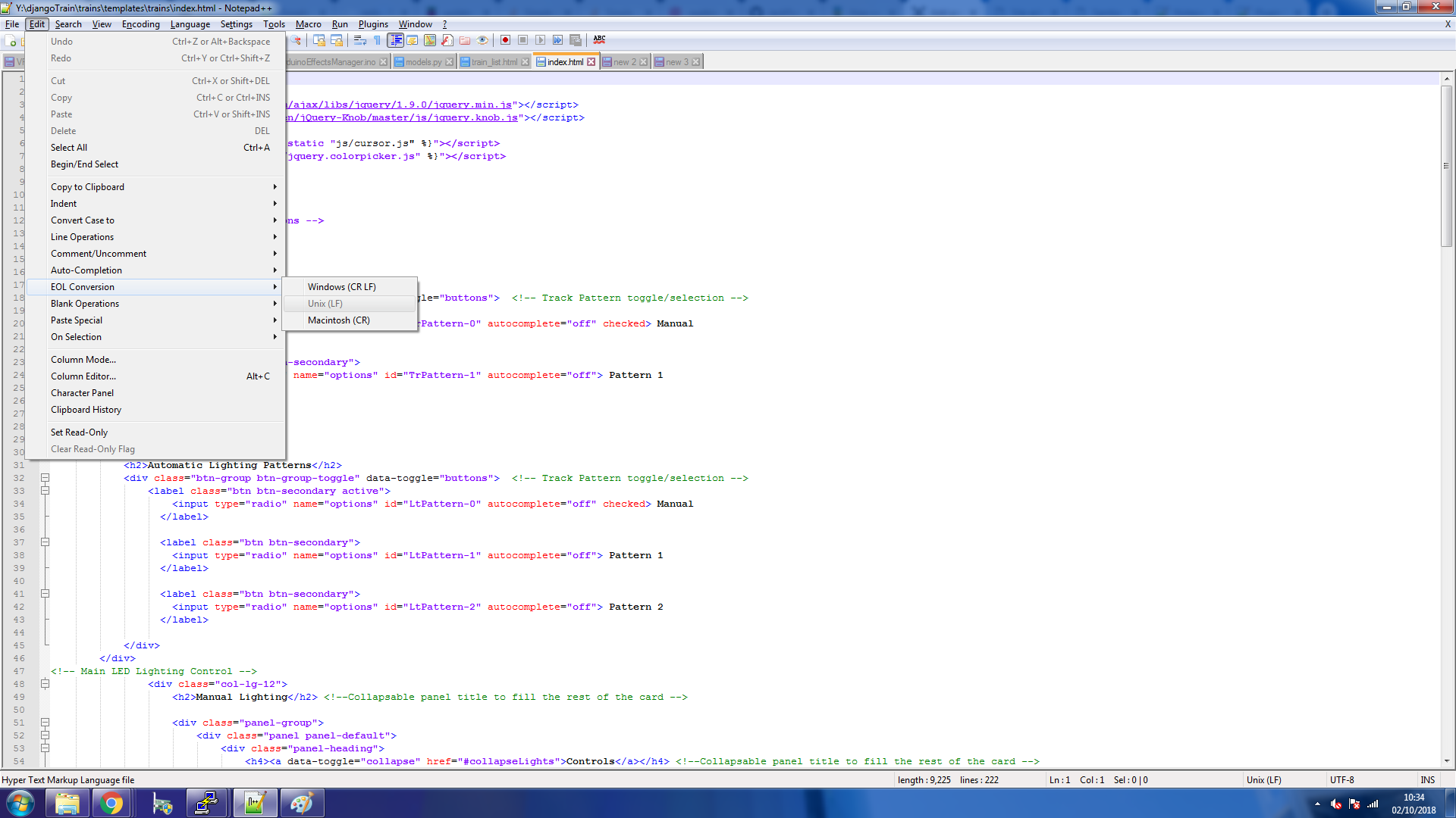
The other critical disadvantage of this method to be aware of is the "EOL" (End of Line) characters in files. Text files created under Windows and Linux add hidden characters to the end of each line of the file. Linux doesn't like the Windows method so if you create a new text file in windows, save it as "py" python file, transfer it to the Pi and then try to run it you'll throw an error complaining about EOL. There's a bash command you can run on the file with the terminal on the Pi but it would be nice if our IDE could take care of that for us.
IDE Choice
So now I can manage files on the Pi, I need something that suits my development requirements for the project. The Pi is running as a central web-server that talks to both the Sprog and the Teensy hardware interfaces. This means I'll be working with Python, HTML, Javascript and potentially others such as bash or shell scripts. While diving around these files I want something that's lightweight, fast and is a bit more advanced than just notepad. Almost like a notepad advanced. Like a notepad + features. Like Notepad++.
![]()
Notepad++ is lightweight, easy to use, supports all the languages I need with colour coding, and can also take care of the End-Of-Line issue when saving files from Windows to the Pi.
![]()
Drawbacks
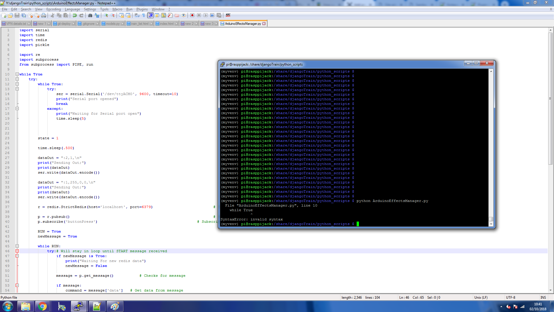
While I'm happy with the setup I'm using there's still a number of drawbacks compared to a more "professional" or commercial setup. There's no debugger in Notepad++ so every time I want to run or test a file I need to either refresh my browser for HTML or for Python I need to open a terminal to the Pi and run the script manually. While this may seem tedious it's actually an easy flow to follow and running python scripts through the terminal results in some half decent error messages when the inevitable mistake is made;
![]()
(I'm missing the ":" at the end of my while True statement)
So for now, this works for me. Your millage may vary..
Not Just Another Coffee Table
Custom coffee table with a DCC train track, automation, LEDs and a web interface