 Dr. Cockroach
The first basic Inv / Not gate being tested for the first time on October 6, 2018
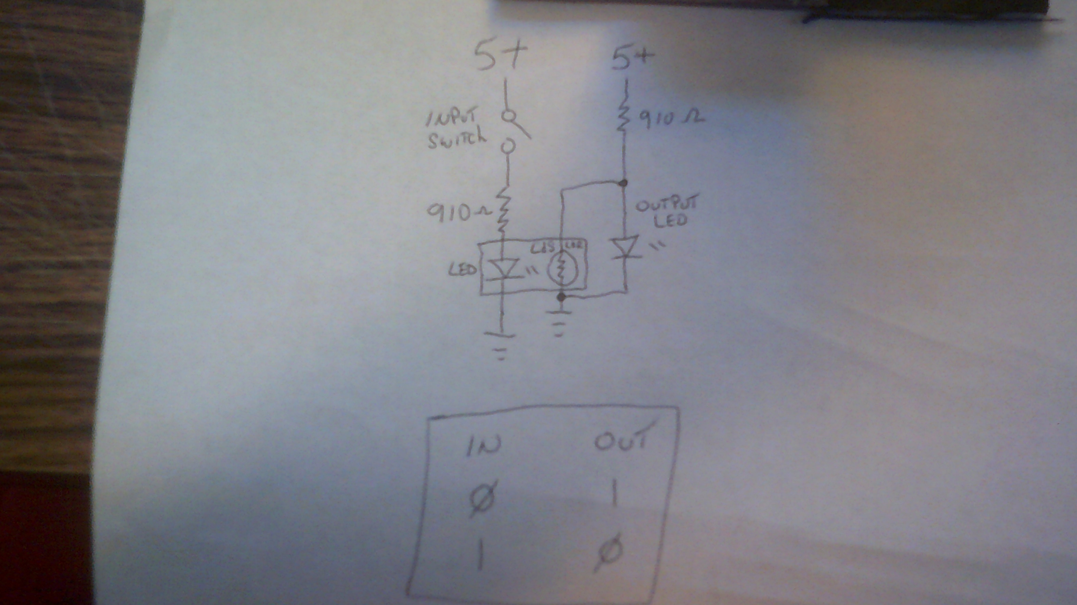
Very basic circuit but it works just like it should.
The output led is for test and demo only. Remove it and take the logic output at the junction between the 910 Ohm resister and the LDR. The output level is about 4.5 volts for a logic one and about 1.5 volts for logic zero. Enough of a voltage swing for the next gate in line to fully function and the best part is that the logic voltage is restored at each output.
Discussions
Become a Hackaday.io Member
Create an account to leave a comment. Already have an account? Log In.