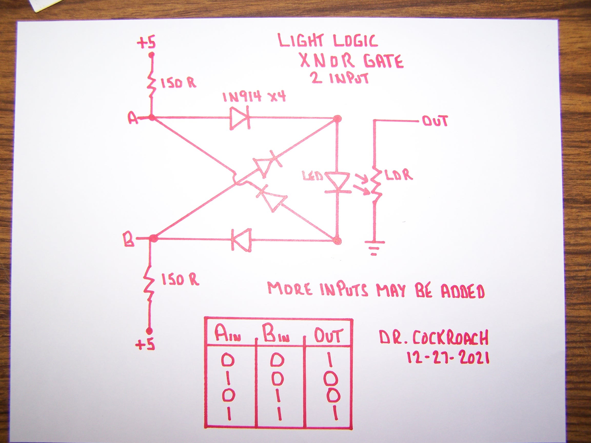
December 28, 2021 - After a bit of an absence I started improving on some of my Light Logic gate circuits. I was never satisfied with how my XNOR gate turned out so I ended up having a dream last night and when I woke up this morning I got to working on what I had dreamed about. The simple change is that I now feed 5 volts to the inputs continuously through a pair of 150R resistors. If there is no input at either A or B then the input is considered HIGH. If either A or B is grounded through a previous gate then the input is LOW. The Out of the LDR can be followed by a Light Logic Inverter gate to create a XOR gate or wired to any other gate as needed. I have this circuit on a bread board and it is working as it should. Remember, with Light Logic the output MUST be through the LDR to ground to be a counted as a solid Zero / Low. Anything else is counted as a One / High

 Dr. Cockroach
Discussions
Become a Hackaday.io Member
Create an account to leave a comment. Already have an account? Log In.