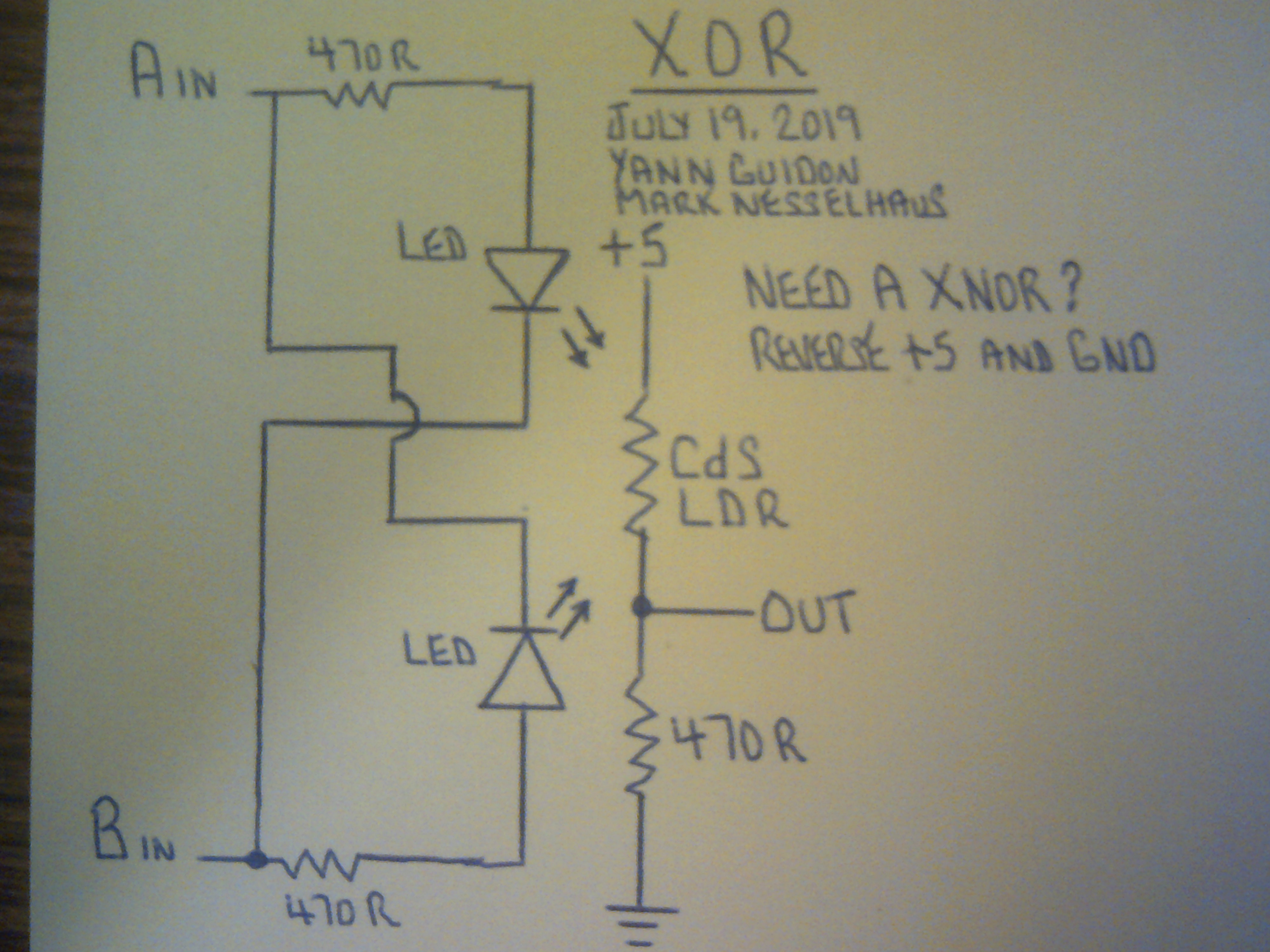
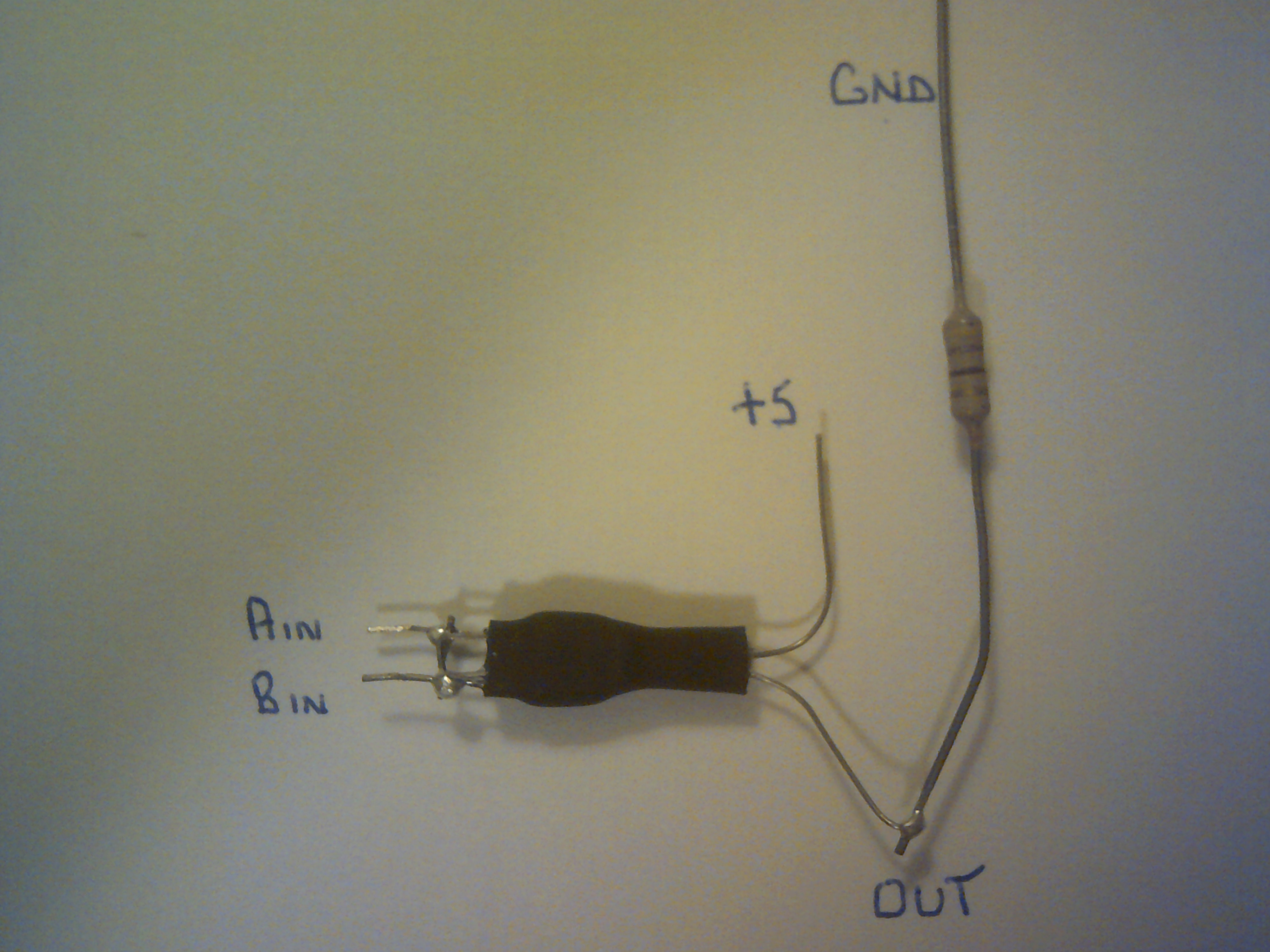
Here is another XOR circuit that I wired and tested last night. Thanks to Yann Guidon for this idea as it does further reduce the parts count. The Input resistors are optional depending on the logic level voltage. For a XNOR, just reverse the +5 and ground. This XOR, once again, has good solid logic levels on the output.


 Dr. Cockroach
Discussions
Become a Hackaday.io Member
Create an account to leave a comment. Already have an account? Log In.
Wow, that's really simple and makes sense. My only worry with these LDR based gates, is that often they require the inputs sink current. I might expect problems when a lot of gates are cascaded together, like if you try to build a computer with it. I hope you can though; that would be pretty cool. I just wish LDR's weren't so slow.
Are you sure? yes | no
Yeah, the CdS LDR speed is going to set some slow speed records but I am trying to brainstorm ways to compensate for the response curve. I expect that I should be able to build something like my IO Cardboard Computer using LL. I did not think I would get this far with it so who knows :-) Cascading poses no problems so far but keeping my fingers crossed :-)
Are you sure? yes | no
@roelh After you said that I blinked and said, yup, he's right about that as far as a three pin led :-D
Are you sure? yes | no
Hi Doc, you might get an even lower component count by using two-pin bi-color leds like this one:
(search: Mouser WP57EGW)
Your 'primary' circuit will now just be the LED and a single resistor !
Are you sure? yes | no
I do happen to have one 3 lead Led that might work. It just amazes me how simple this became in so short a time :-)
Are you sure? yes | no
A two-pin bicolor LED has both internal LEDs connected in opposite position, that can be used in your circuit. But a 3-pin bi-color LED has either both anodes, or both cathodes connected to each other, which makes it impossible to use in your circuit.
Are you sure? yes | no