Today I built the SWR bridge on the breadboard, and adapted the arduino sketch to read the FWD and REV voltages on two analog pins.
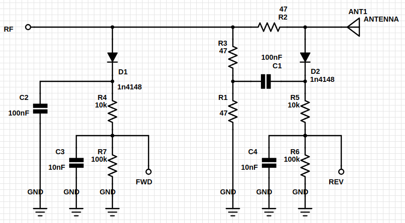
The SWR bridge design is given in the following schema, and taken from an antenna analyzer build by the NJQRP club. A link to the article is given in the links section.

| chose this design solely because of its simplicity (only resistors, caps and diodes). The analyser in the article also uses an op amp to boost the signal on the FWD and REV ports, and to counter the low impedance on the A/D converter used in their design. In my case the input pins of the arduino have a high enough impedance and the signal should be significant enough to get at least some reading, so in this stage I'm omitting the op amp for simplicity.
The FWD and REV ports are connected to arduino pins A0 and A1 respectively, and the SWR value is calculated using SWR = (FWD+REV) / (FWD-REV).
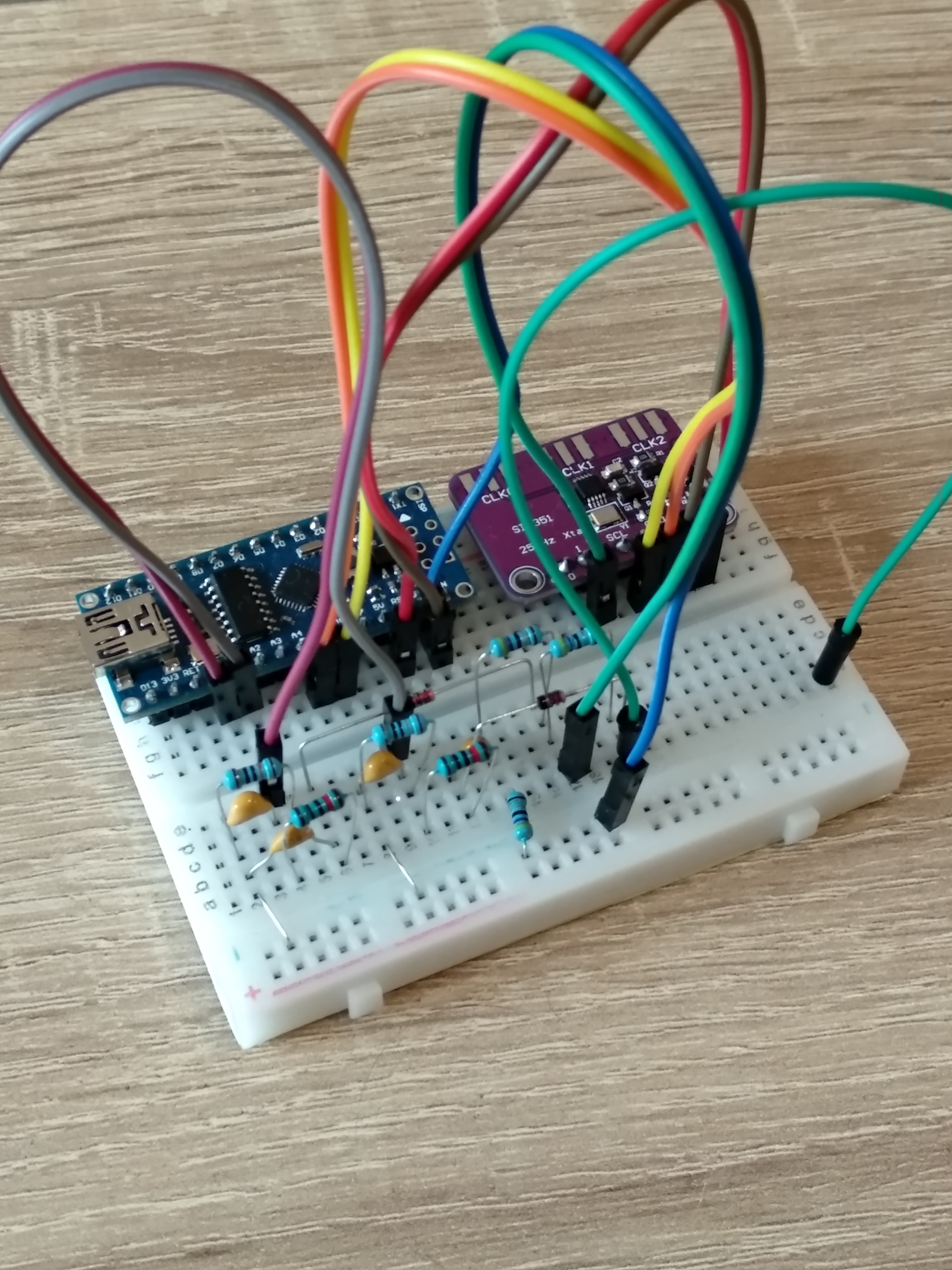
The breadboard with the arduino, si5351 and swr bridge looks like this:

I know it will give horrible performance on such a board, but i just wanted to see if the concept works.
The swr_sweep.py script is also adapted in the repo, and when i sweep the 27-29MHz range the swr bridge is reporting a standing wave ratio between 3.5:1 and 4:1. Looks promising!
Next i have to find an antenna or so with a known resonance frequency, and test if this little contraption can find the sweet spot.
 biemster
Discussions
Become a Hackaday.io Member
Create an account to leave a comment. Already have an account? Log In.
This is exactly what I've been looking for. So many of the HF antenna analyzers don't use the Si5351, and I happen to have an extra one on hand! Any update on testing accuracy?
Are you sure? yes | no
No not yet, I'm still looking for an antenna/load with known swr, since I don't have a professional analyzer. But this is my top project at the moment, so there will be an update soon for sure.
Are you sure? yes | no