CONCEPTS
Before continuing, it is important to understand what is being wired. A logical arithmetic unit (ALU) is a digital circuit that calculates arithmetic operations (addition, subtraction, multiplication, etc.) and logical operations (AND, OR, NOT, etc.) between values that are provided to it.
Broadly speaking, a 2-bit ALU with two operands (A and B) behaves as in the diagram. Each bit of the ALU is processed in the same way, with the exception of the carry bit.
The inputs A and B are connected to 4 gates (XOR, AND, OR and a complete adder) with which logical and arithmetic operations will be performed.
At the exit of these gates, the multiplexing of the data is expected. The each gate output is converted into input, to these are added the OP inputs that determine which of the functions will be performed:
OP = 000 → XOR
OP = 000 → AND
OP = 000 → OR
OP = 000 → Sum
For the realization of our ALU we use 5 types of different logic gates:
NAND: produces a false output only if all its inputs are true; therefore, its output is complementary to that of the AND gate
OR: when all its inputs are at 0 (zero) or at LOW, its output is at 0 or at LOW, whereas when at least one or both inputs are at 1 or on HIGH, its OUTPUT will be on 1 or on HIGH.
MUX: combinational circuits with several inputs and a single data output. They are equipped with control inputs capable of selecting one, and only one, of the data inputs to allow their transmission from the selected input to said output.
XOR: implements the exclusive o; that is, a true output (1 / HIGH) results if one, and only one of the inputs to the gate is true. If both inputs are false (0 / LOW) or both are true, it results in a false output.
SUM: digital circuit that performs the addition of numbers.
BLOCK DIAGRAM
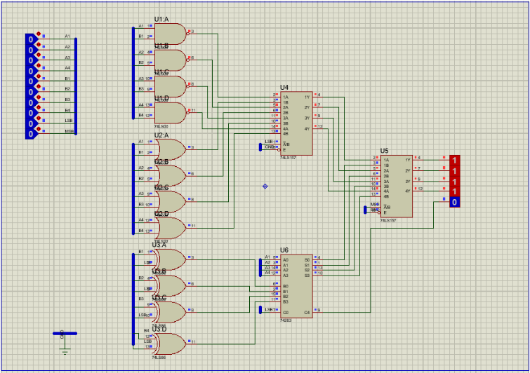
The block diagram provided in the presentation of practice 1 shows the two 4-bit inputs entering the logical units and the arithmetic ones. From the instruction line you select the result of the results is displayed with the following combination:
Opcode | Instruction |
00 | A NAND B |
01 | A OR B |
10 | A + B |
11 | A - B |
At the time of assembly, the data selectors were omitted and the outputs are shown by means of 8 LEDs where the output of the arithmetic unit and the logic are observed at the same time.
In reality, the entries are composed by DipSwitch that send the data and instructions to a specific combination of logic gates that was explained above. At the output of these gates is a multiplexer that indicates in the yellow LEDs the result of the logical operations and in the lower part the result of the addition or subtraction.
SCHEMATIC

In our circuit we use the PULL-UP connection type, which consists of connecting the resistors to the voltage source and the resistors the signal we want to send, as well as the DIPSWTCH, ending with a ground connection.
The gates have different arrangement of entrances and exits. The NAND, OR and XOR gates have the same arrangement, which was something that made things a little easier for us since we did not have to change the designs. The MUX and the Sumador to have different functions if they had a different arrangement, but easy to understand.
For the assembly we did not want to repeat colors to avoid errors due to confusion when making the wiring, so we made a small color code, which does not follow the resistance code, but it served us well enough to have an order. Which is the following:
Red---------------------------VCC
Black-------------------------GND
Blue--------------------------1
Gray-------------------------2
Green-----------------------3
Yellow-----------------------4
Purple-----------------------5
Orange---------------------6
White------------------------7
Blue pinstripe-------------8
Yellow pinstripe----------LSB/C4
Gray pinstripe-------------Mux A1B1
Purple pinstripe-----------Mux A2B2
Orange pinstripe---------Mux A3B3
White pinstripe------------Mux A4B4
Red pinstripe---------------Salida 1 y 3
Green pinstripe-----------Salida 2 y 4
 Lilia Lobato