 Beaglebreath
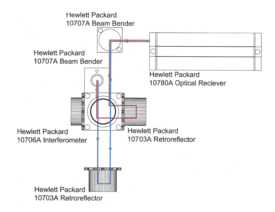
(sorry for the spelling error in the picture above...)
The picture above is my arrangement of the optical parts of this project. All parts remain stationary, with respect to each other, except for the Retroreflector shown at the bottom of the picture. The relative motion of the retroreflector toward or away from the interferometer will cause a Doppler shift in the reflected light frequency.
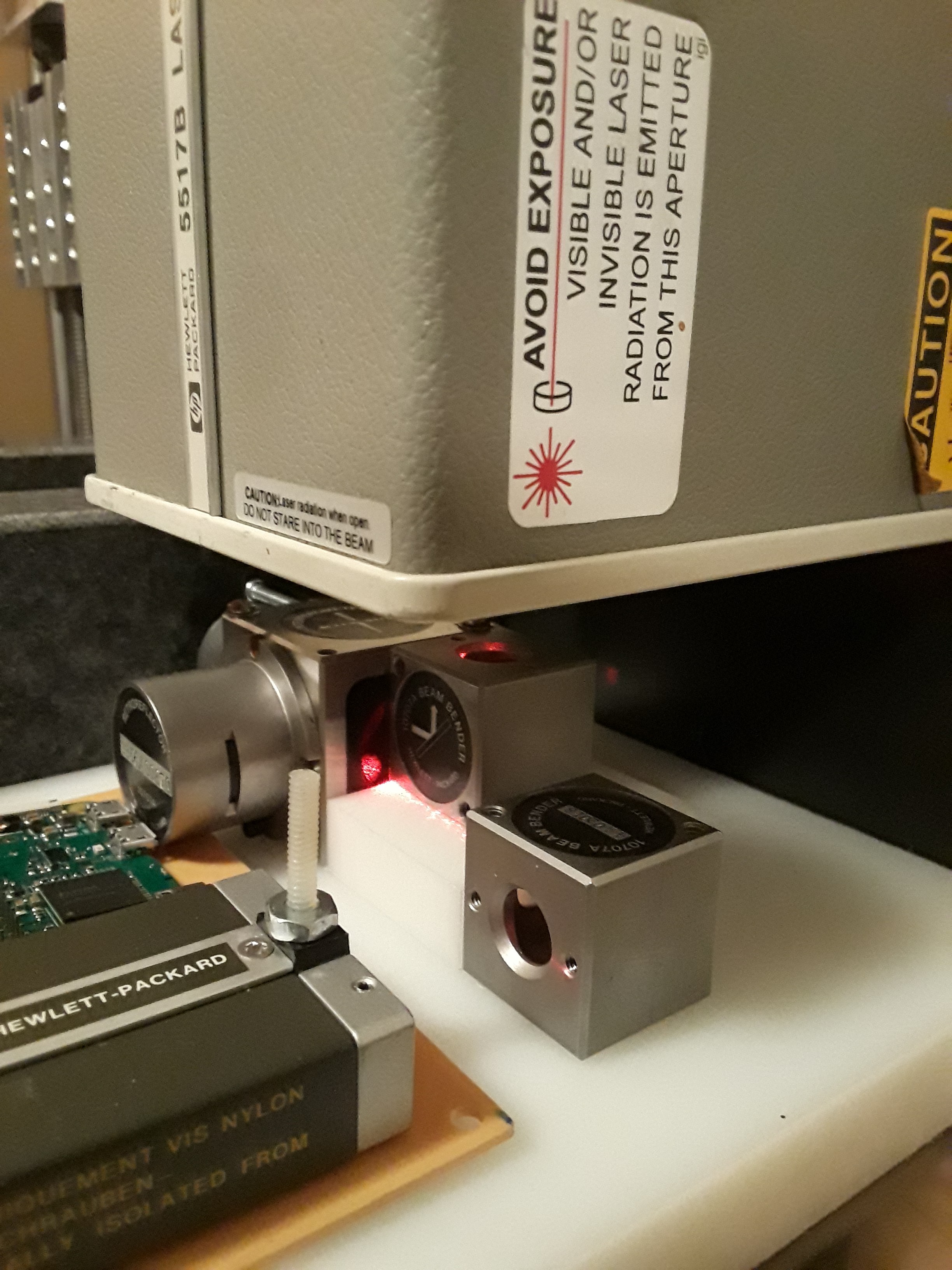
Light enters the optics from a Laser. The laser is a HP 5517B, which is magical. The laser light emitted is comprised of two slightly different frequencies, and are deliberately shifted out of phase by 90°. As I have been playing with the laser from time to time, I realized that the two frequencies and a 90° phase shift is what is needed for radio heterodyne circuits as well as radio mixer circuits.
The HP 5517B laser uses the Zeeman Effect to generate the two frequencies. The Zeeman Effect is a result of slightly different energy levels that are available for electrons associated with the Helium and Neon gasses in the laser. An internal magnetic field is used in the laser to affect the electron and their Electron Spin property. The Electron Spin also magically generates separate polarities of the light depending on the Spin orientation.
The HP 5517B also houses an internal optical receiver. The internal optical reciever detects the two light frequencies/polarities and mixes them to produce an electrical signal which is provided on a connector on the rear of the laser housing. This signal is a TTL level square(ish) wave at about 2.145 MHz. This wave is not effected by the external optics and/or any motion of the optics. This signal will serve as a REFERENCE signal in a mixer circuit or a quadrature encoder circuit.
The light from the laser has two polarities, shifted by 90°. The remaining optical components are polarized so that they can manipulate the polarized light.
- One of the polarities is directed into the optical interferometer, and is reflected onto a stationary retroreflector. The light is reflected from the retroreflector back into the interferometer, which then directs the light toward the external optical receiver. This polarized light path passes through optics that are stationary and therefore do not have a Doppler shift.
- The other polarity is able to pass through the interferometer without being manipulated in any way. The light proceeds to the movable retroreflector. The retroreflector sends the light ray back in the direction it arrived from. Again the light passes through the interferometer and follows the same path as the other polarity on to the optical receiver.
The two polarized light beams arrive at the optical receiver. (if I understand correctly) the beams are each shifted 45°, so that they share the same polarity and can finally mix together. The optical mixing is analogous to mixing radio frequencies. A sum of the two frequencies is produced (and ignored) and a difference frequency is produced. The difference frequency is related to the 2.145 MHz REFERENCE that I mentioned earlier.
- If the moveable mirror is not moving; then the mixed light frequencies produce a difference frequency equal to the REFERENCE.
- if the movable mirror is moving, then the mixed difference frequency will be equal to the (REFERENCE ± Doppler Shift). The receiver produces an electrical signal from it's connector with it's own TTL level square(ish) wave. This signal is refered to as MEAS.
Discussions
Become a Hackaday.io Member
Create an account to leave a comment. Already have an account? Log In.