The Street Sense device can operate with two power sources:
- Stand-alone battery power
- USB power
The Lolin D32 Pro board provides much of the required circuitry to manage power between the two sources.
- When 5V USB power is present the lithium polymer battery (LiPo) battery is recharged.
- With stand-alone operation the LiPo battery provides power to the unit
One feature of the Lolin board is external USB and battery pins. When the board is plugged into a USB source, the 5V USB voltage is presented at the USB pin. Similarly, under stand-alone battery power, the 3.7V battery voltage is presented at the BAT pin. These external pins will be used to power the Plantower particulate sensor.
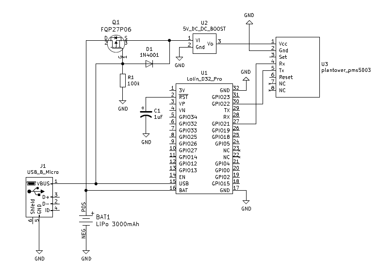
The Plantower particulate sensor requires a 5V supply to power the internal fan. To provide this voltage under 3.7V battery power conditions a DC-DC boost converter is used, shown in the schematic below (U2).
The circuit shown below will block battery current when USB power is present. The obvious benefit is that battery capacity is maintained when USB power is present. The less obvious benefit is that it satisfies an important design constraint for the Lolin's internal battery charge management IC (TP4054) -- this IC requires that minimal load current is present on the battery during a recharge cycle.
How does this circuit work? The P-Channel MOSFET (Q1) turns OFF when USB power is present at the MOSFET Gate. This blocks the battery from supplying power to the boost converter. The battery management IC sees minimal load.
Note: this circuit was taken from the battery management design shown in the Lolin D32 Pro device schematic. The Lolin circuit has a similar objective of removing the internal 3.3V voltage regulator from the battery charging circuit when the device is plugged into USB.

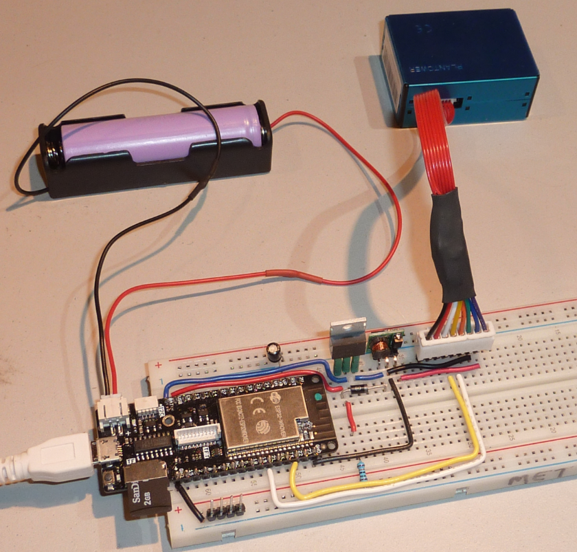
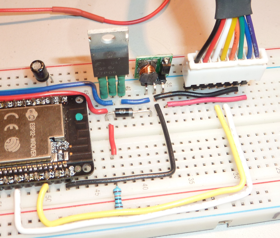
Here are some photos of the prototype circuit built up using a breadboard.


Testing
I copied a MicroPython program into the ESP32 that reads the particulate sensor and switches it between Active and Standby modes. The BAT pin current was measured when the unit was under battery and USB power. This current flows through the MOSFET and into the boost converter. A uCurrent Gold device was used in the current path to eliminate the effects of the multimeter burden resistance.
Results are shown in the table below. The BAT current of 2.0mA under USB power will not interfere with the charge termination criteria of the Lolin battery management IC.
| Plantower Sensor Mode | Power Source | BAT pin current [mA] |
|---|---|---|
| Active | Battery | varies 95-140 |
| Active | USB | 2.0 |
| Standby | Battery | 12.5 |
| Standby | USB | 0.0 |

 Mike Teachman
Discussions
Become a Hackaday.io Member
Create an account to leave a comment. Already have an account? Log In.