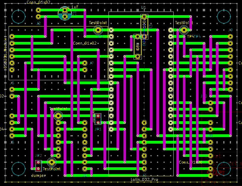
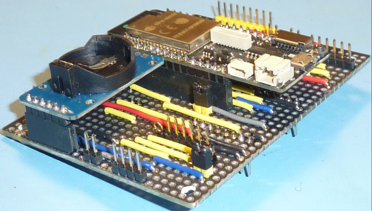
The next transformation from breadboard to PCB is the CPU Module. If you look at the schematic it might be better called a "connector module" or a "glue module".
This hardware module serves to connect all the peripherals and other hardware modules to the ESP32 microcontroller. Some connectors terminate at switches and buttons which will be mounted on a user accessible panel. Other connectors terminate at the sensor units: I2S microphone and the PCBs holding the air quality sensor units.
The PCB construction uses stripboard techniques with KiCad as the layout tool.
Some notable PCB design considerations:
- jumpers for the battery and USB inputs - to allow measurement of current for various operating modes.
- test points on all power and ground signals
- three connectors are placed on the back side of the PCB. These connectors service hardware modules that are located inside the external enclosure. This construction choice exploits a key benefit of plated through-hole stripboard construction - the ability to place components on both sides of the PCB.
Layout

Populated board

 Mike Teachman
Discussions
Become a Hackaday.io Member
Create an account to leave a comment. Already have an account? Log In.