0%
0%
 Jarrett
Become a Hackaday.io member
Already have an account? Log in.
Just one more thing
To make the experience fit your profile, pick a username and tell us what interests you.
Pick an awesome username
hackaday.io/
Your profile's URL: hackaday.io/username. Max 25 alphanumeric characters.
Pick a few interests
Projects that share your interests
People that share your interests


 Kevin Arne
 deʃhipu
 Jorj Bauer
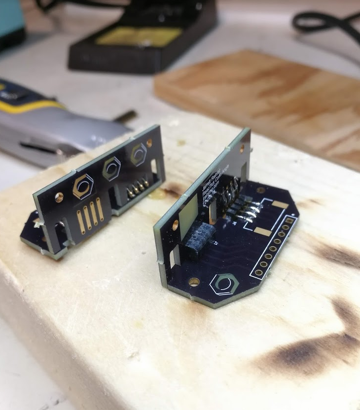
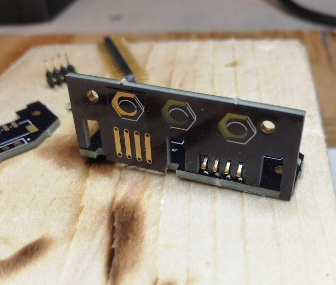
How about a PCB that adapts screw terminals for STEP, DIR, ENABLE, and GND to the Stepstick / Pololu pinout? Having a row of four screws plugged into Stepstick sockets would make it very easy to use RAMPS and others with big, high power motor drivers.